MAN00000772_SI-G200BB_SVCPDFA.pdf - 第178页
HLGB-10203-01 Acquiring Mounting Stro ke Setu p Click the XY button on the Acquiring mounting stroke screen. XY Axis screen is disp l a yed. Click the Jog Move button. Press the cursor key to jog move the head unit onto …
HLGB-10203-01
Acquiring Mounting Stroke Setup
When installing the nozzle, insert it while
slowly turning.
After inserting the nozzle, check that it is not
drawn out by pulling downward.
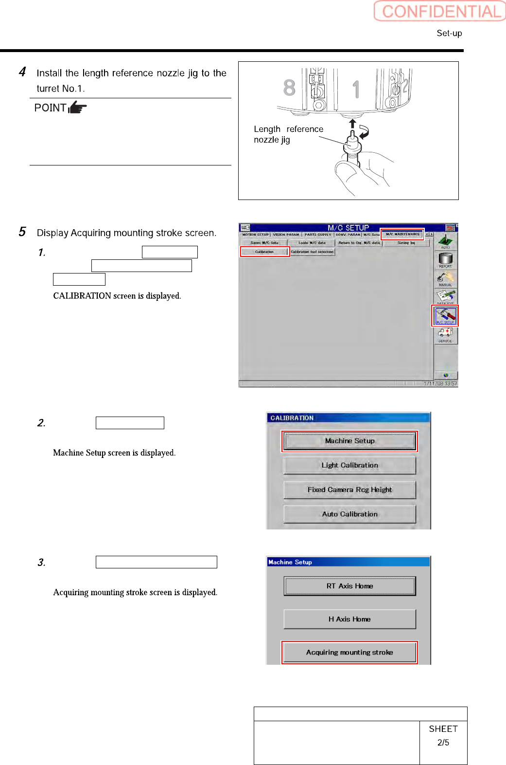
Click in an order of M/C SETUP
menu M/C MAINTENANCE tab
Calibration button.
Click the Machine Setup button on the
CALIBRATION screen.
Click the Acquiring mounting stroke
button on the Machine Setup screen.
HLGB-10203-01
Acquiring Mounting Stroke Setup
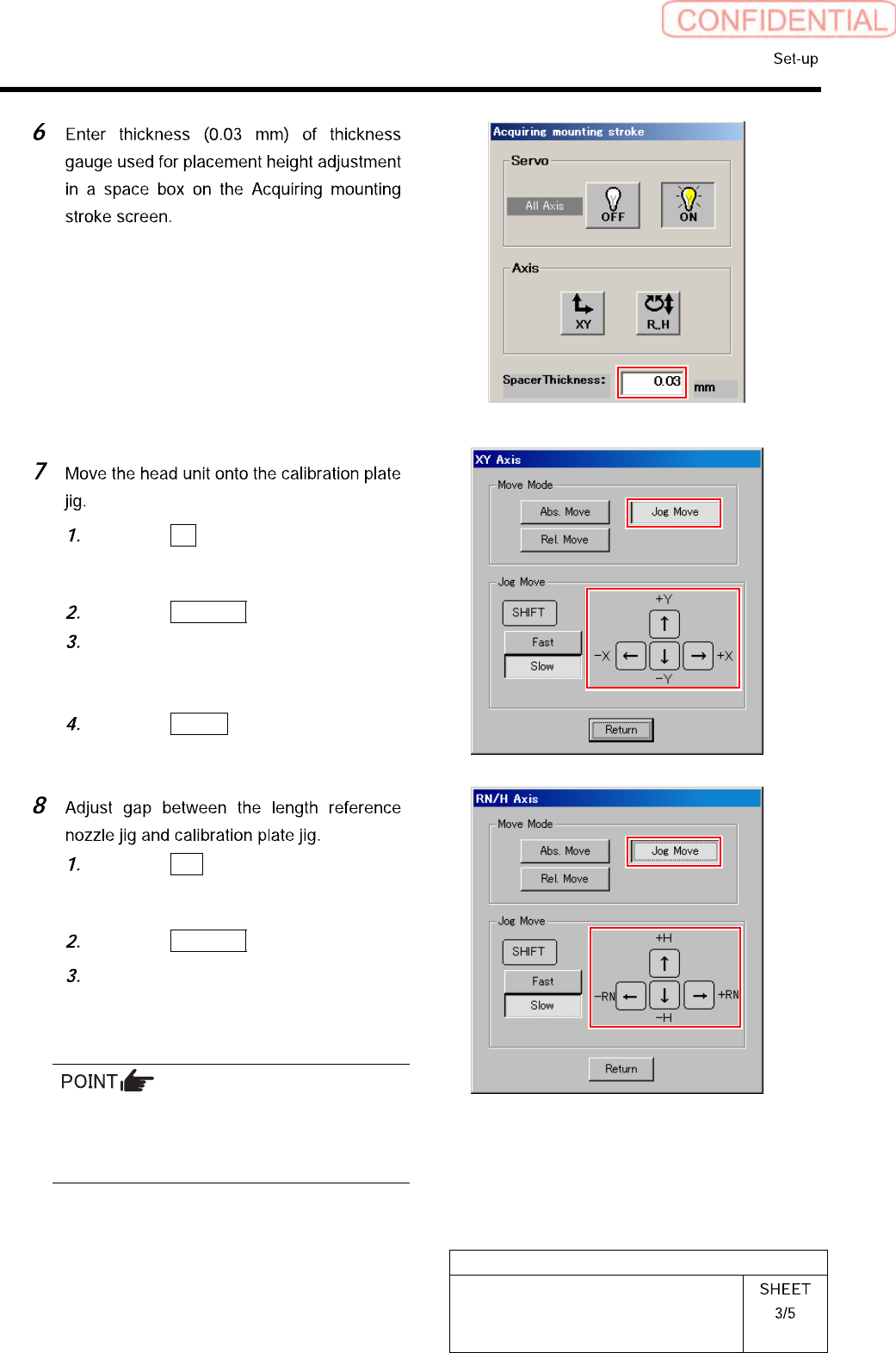
Click the XY button on the Acquiring
mounting stroke screen.
XY Axis screen is displayed.
Click the Jog Move button.
Press the cursor key to jog move the
head unit onto the calibration plate
jig.
Click the Return button to return to
the Acquiring mounting stroke screen.
Click the R.H button on the Acquiring
mounting stroke screen.
RN/H Axis screen is displayed.
Click the Jog Move button.
Press the downward cursor key and
lower until the gap between the length
reference nozzle jig and calibration
plate jig becomes 0.03mm.
Slowly lower by Jog slow move while checking
the nozzle position so that the length reference
nozzle jig does not collide he calibration plate
jig.
HLGB-10203-01
Acquiring Mounting Stroke Setup
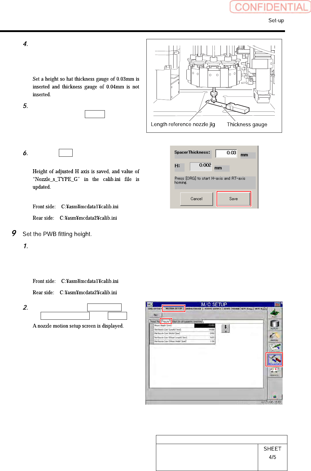
Check the gap between the length
reference nozzle jig and calibration
plate jig using thickness gauge of
0.03mm.
After completing to adjust the gap of
0.03mm, press the Return button on
the RN/H Axis screen to return to the
Acquiring mounting stroke screen.
Click the Save button on the Acquiring
mounting stroke screen.
< Storing area of calib.ini file >
Record the value of
NOZZLE_S_TYPE_G described in
calib.ini.
< Storing area of calib.ini file >
Click in an order of M/C SETUP menu
MOTION SETUP tab Nozzle tab.