MAN00000772_SI-G200BB_SVCPDFA.pdf - 第298页
HLGB-10404-01 Adjustment of H A xis Upper End OT Sensor (H-CCW) Perform this working on b o th he ads on t he front side and rear side. [Necessary jigs] • H Axis sensor adjusting Jig (L=26.6 mm, 26.5 mm) • Thickness gaug…
HLGB-10403-01
H Axis Gear Z-phase Matching
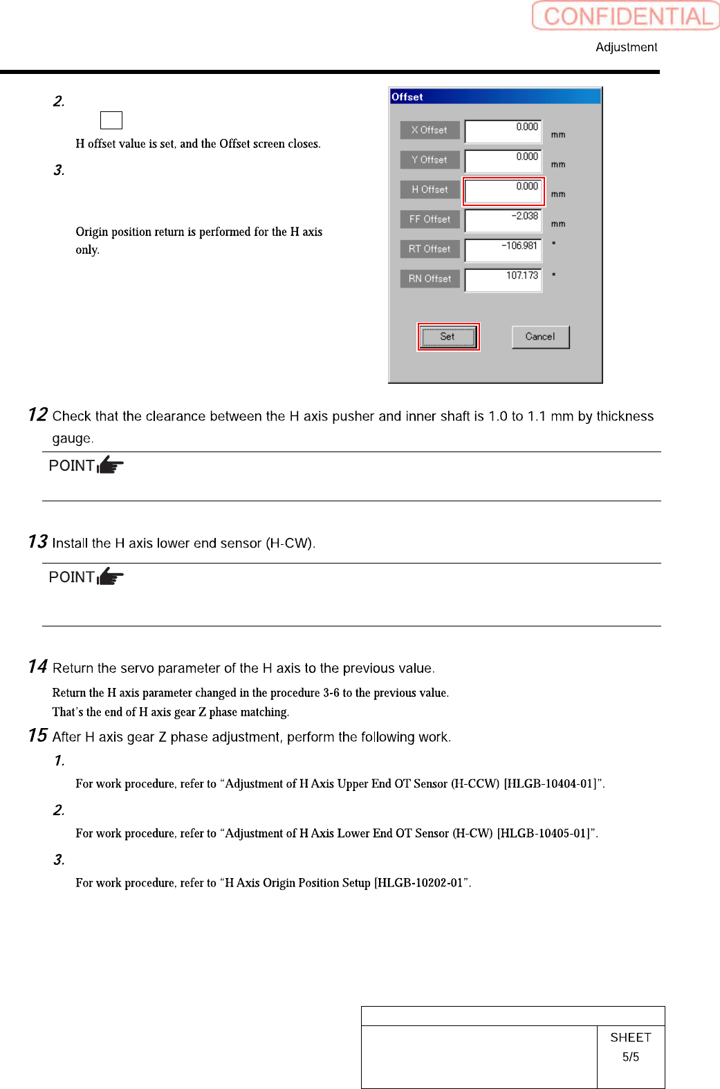
Input “0” in the H Offset box, and click
the Set button.
Press the [ORG] button on the
operation panel with the RN/H axis
screen displayed.
Unless the clearance is 1.0 to 1.1 mm, it is necessary to re-perform “H axis origin position setup”.
Perform position adjustment of the lower end sensor (H-CW) in the post-process of “Adjustment H axis
lower end OT sensor (H-CW)”.
Adjust OT sensor at the upper end of H axis.
Adjust OT sensor at the lower end of H axis.
Set H axis origin position.
HLGB-10404-01
Adjustment of H Axis Upper End OT
Sensor (H-CCW)
Perform this working on both heads on the front side and rear side.
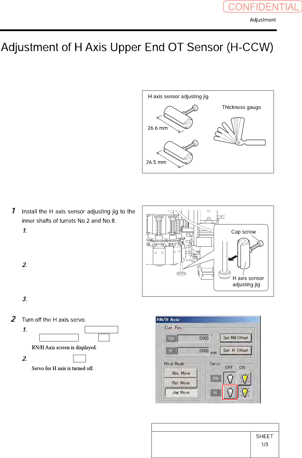
[Necessary jigs]
• H Axis sensor adjusting Jig
(L=26.6 mm, 26.5 mm)
• Thickness gauge (t=1.6 mm)
[Procedure]
Push down the inner shaft of the
turret No.2 and pinch the H axis
sensor adjusting jig (L=26.6 mm)
between the turret and inner shaft.
Push down the inner shaft of the
turret No.8 and pinch the H axis
sensor adjusting jig (L=26.5 mm)
between the turret and inner shaft.
Remove the cap screw for H axis
sensor adjusting jig.
Click in an order of M/C SETUP menu
ORG OFFSET tab R.H button.
Click the servo OFF button for H axis.
HLGB-10404-01
Adjustment of H Axis Upper End OT
Sensor (H-CCW)
Keep the cap screws (2-M3) in temporarily
tightened state.
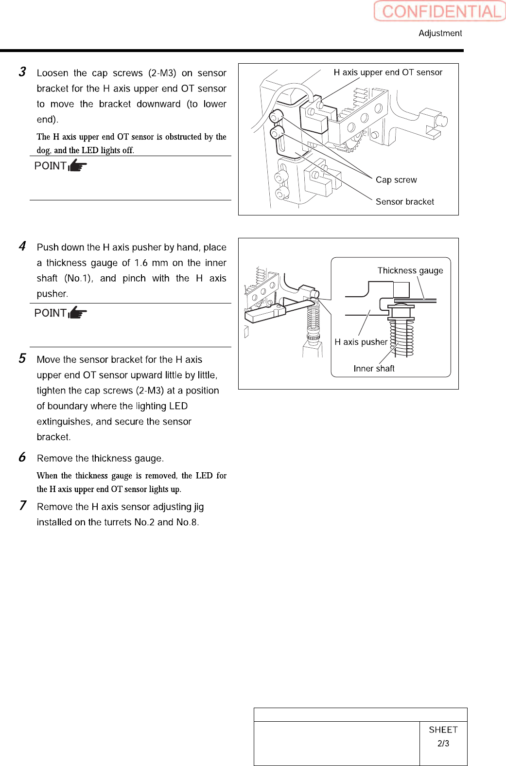
When pinching the thickness gauge, slightly
bring up the inner shaft from the lower.