MAN00000772_SI-G200BB_SVCPDFA.pdf - 第201页
HLGB-10208-01 Pickup Check Camera Setup [Lateral alignment] ↓ Fix the Pickup check camera with pressing it against upward. Press the [ORG] button on the operation pane l t o p e rf o rm origin position return. Remove th …
HLGB-10208-01
Pickup Check Camera Setup
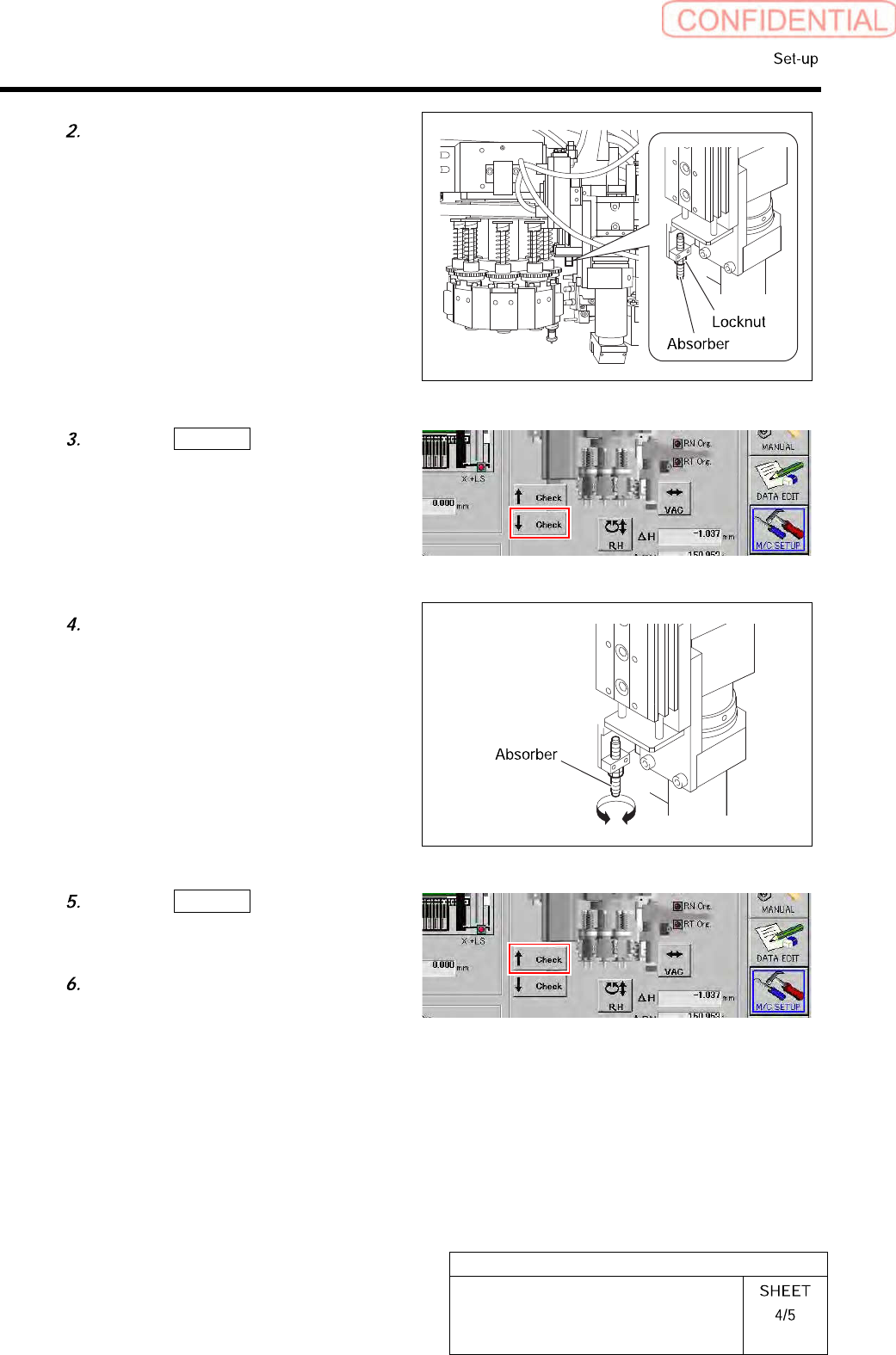
Loosen the locknut for the absorber.
8
7
6
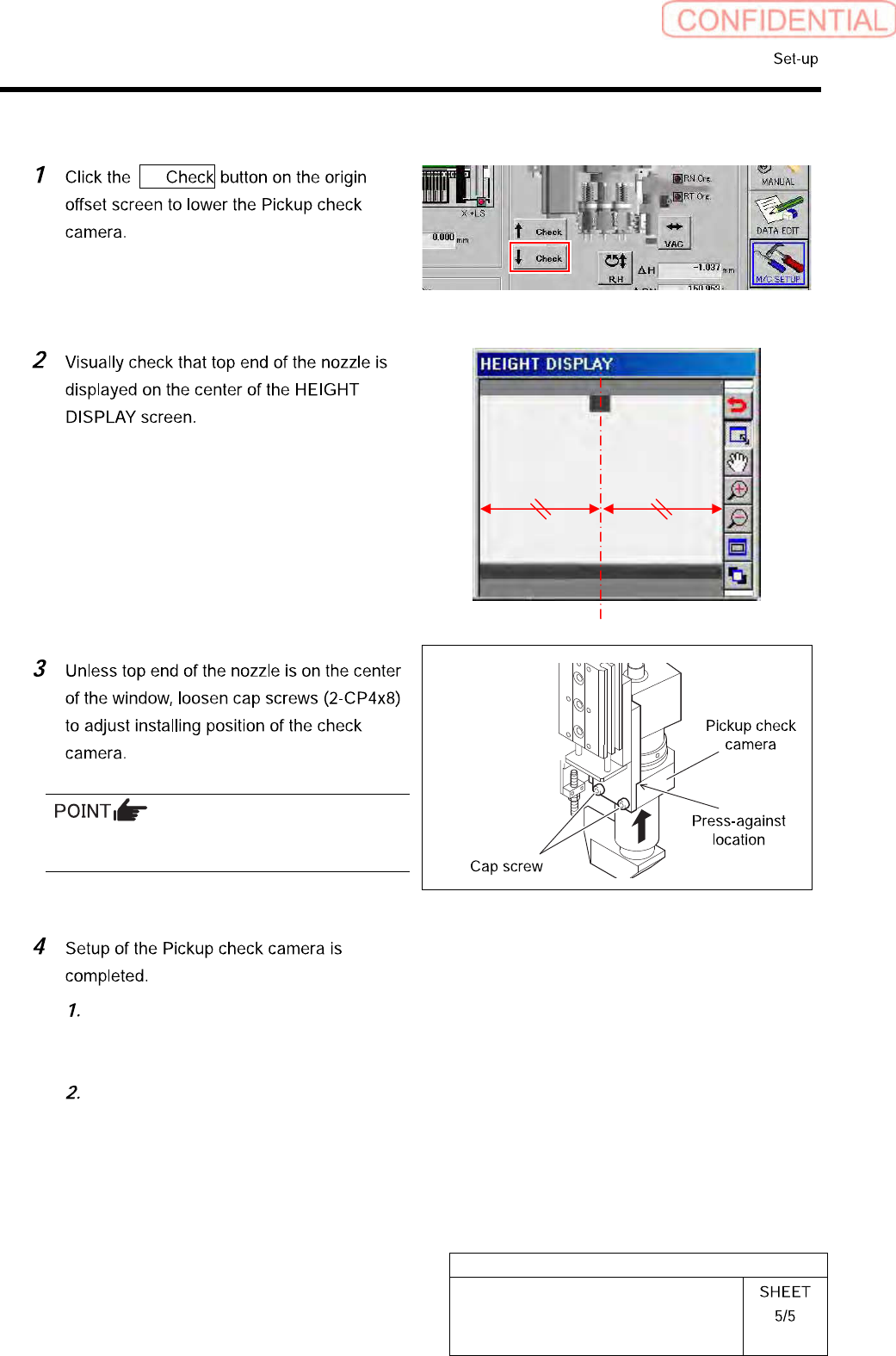
Click the ↓ Check button on the
origin offset screen to lower the Pickup
check camera.
Turn the absorber to adjust the
protrusion amount.
Click the ↑ Check button on the
origin offset screen to raise the Pickup
check camera again.
Tighten the locknut for the absorber.
HLGB-10208-01
Pickup Check Camera Setup
[Lateral alignment]
↓
Fix the Pickup check camera with pressing it
against upward.
Press the [ORG] button on the
operation panel to perform origin
position return.
Remove the length reference nozzle jig
from the turret No.1.
HLGB-10301-01
PWB Camera Light Calibration
Perform this working on both heads on the front side and rear side.
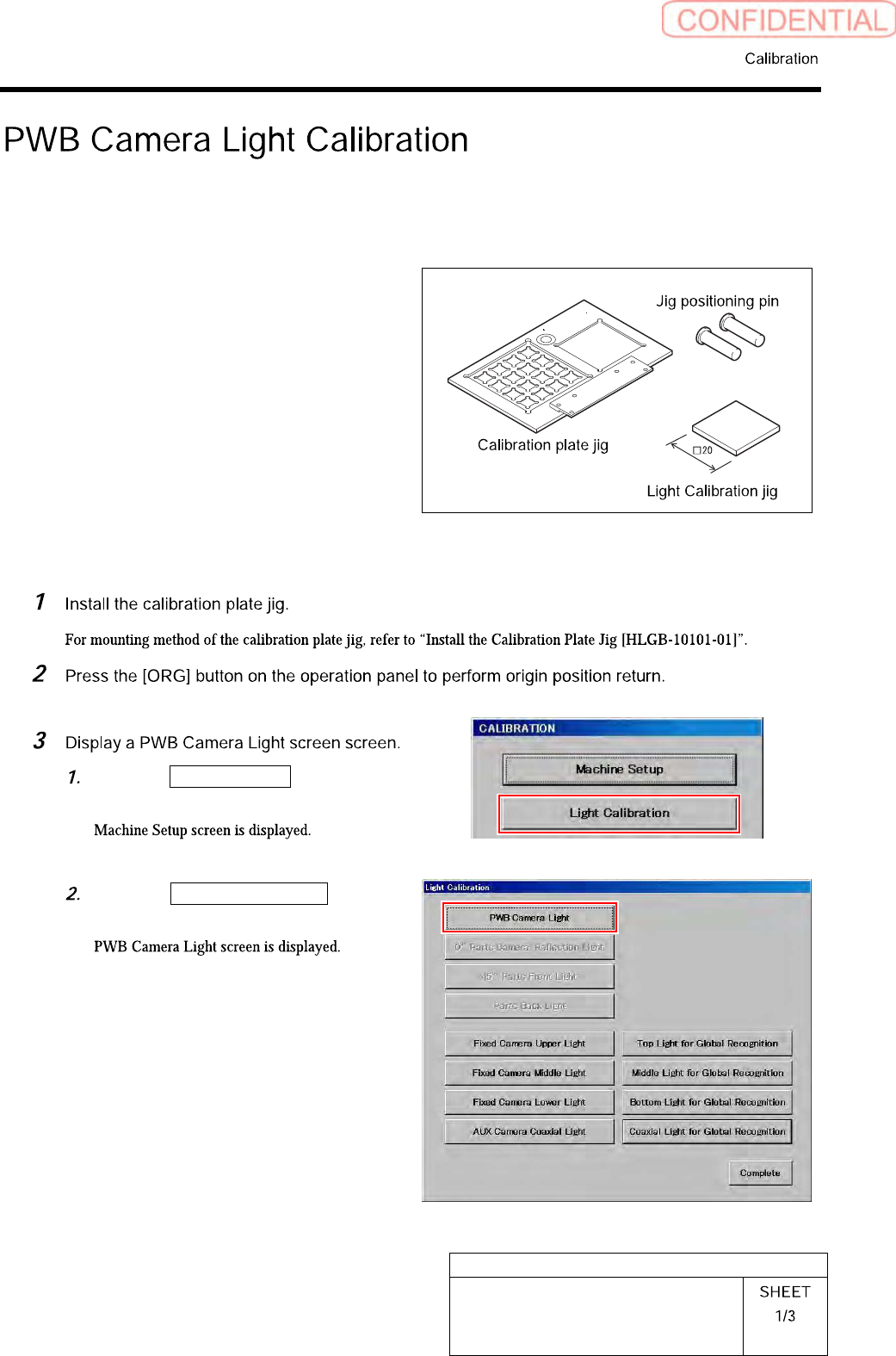
[Necessary jigs]
• Calibration plate jig
• Jig positioning pin
• Light Calibration jig
[Procedure]
Click the Machine Setup button on the
CALIBRATION screen.
Click the PWB Camera Light button
on the Light Calibration screen.