MAN00000772_SI-G200BB_SVCPDFA.pdf - 第244页
HLGB-10310-01 Fixed Camera Rcg Height Calibration Close the calibratio n menu screen to return the unit to the origin. Remove the fixed camera j i g ba se an d length reference nozzle jig. Install the cool i ng f a n for…
HLGB-10310-01
Fixed Camera Rcg Height Calibration
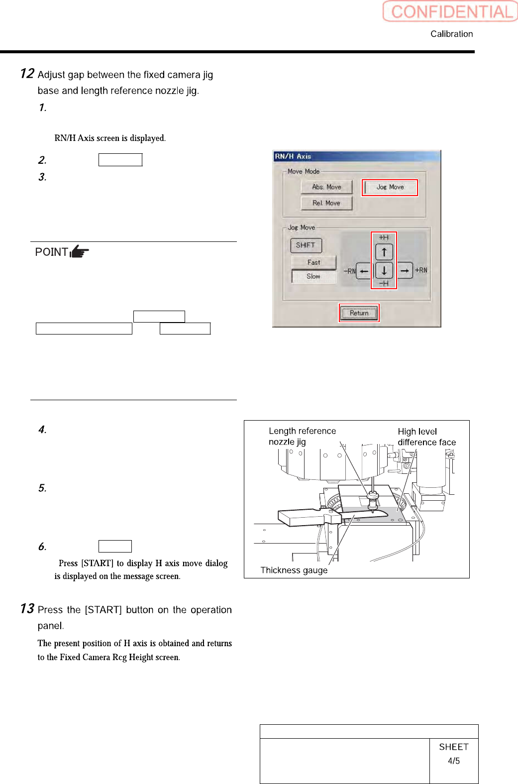
Press the [START] button on the
operation panel.
Click the Jog Move button.
Press the downward cursor key to
lower the length reference nozzle jig to
height of 0.03mm above the fixed
camera jig base (high level difference
face).
If any error occurs when lowering the length
reference nozzle jig, change the negative values
of the H axis software limit to remedy as
follows.
Click in an order of the M/C SETUP menu
MOTOR PARAMETER tab Axis param. tab
and change the negative value of H axis
software limit from [-15.0] to [-16.0].
After fixed camera rcg height is completed, be
sure to return the value of software limit to the
original value.
Check the gap between the length
reference nozzle jig and fixed camera
jig base (high level difference face)
using thickness gauge of 0.03mm.
After adjusting the gap, pull out the
thickness gauge and lower the H axis
by 0.03 mm (three click) by Low speed
Jog Move.
Click the Return button.
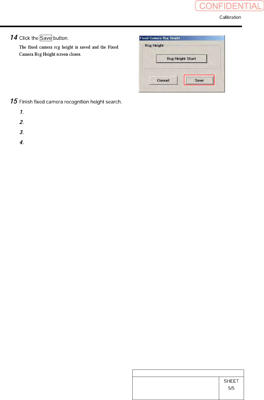
“ ”
HLGB-10310-01
Fixed Camera Rcg Height Calibration
Close the calibration menu screen to return the unit to the origin.
Remove the fixed camera jig base and length reference nozzle jig.
Install the cooling fan for fixed camera to the previous position.
Install the shooter and the lower cover.
HLGB-10311-01
Pickup Position Setup
Pickup position setup can be performed at three locations on the front cassette table (Z106, Z120,
Z139) and at three locations on the rear cassette table (Z106, Z120, Z135).
Perform pickup position setup for tray specification only on the rear side cassette table (Z101, Z108,
Z117).
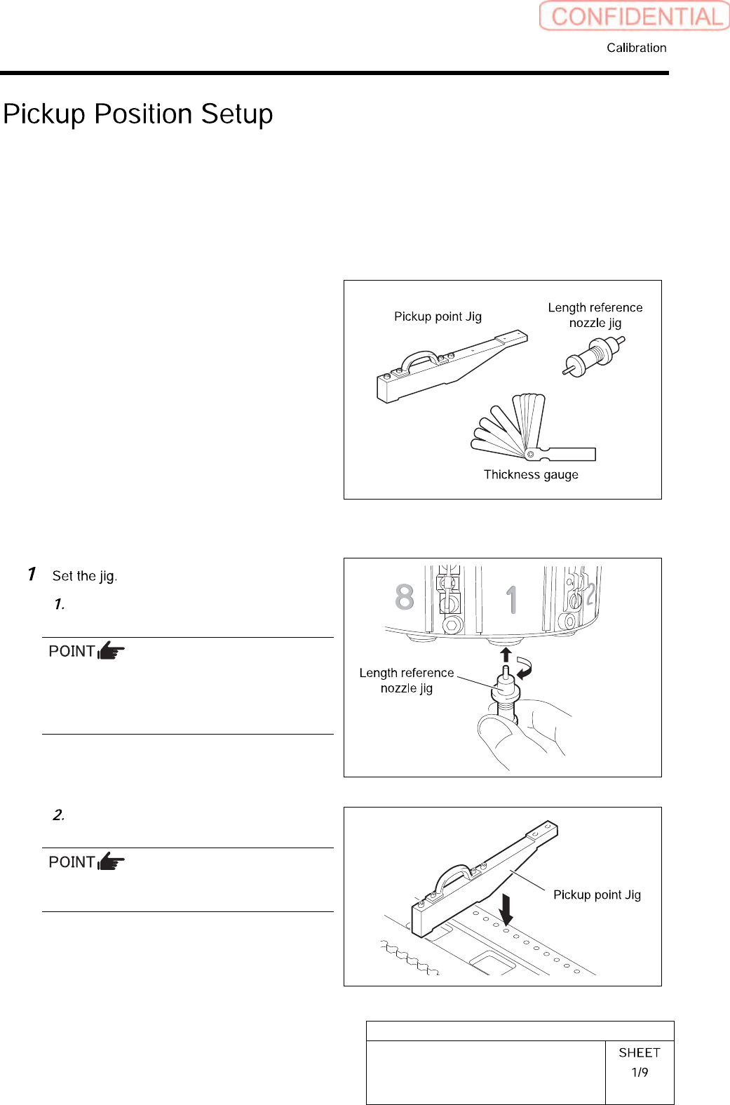
[Necessary jigs]
• Pickup point Jig
• Length reference nozzle jig
• Thickness gauge
[Preparation before work]
Install the length reference nozzle jig
to the turret No.1.
When installing the nozzle, insert it while
slowly turning.
After inserting the nozzle, check that it is not
drawn out by pulling downward.
Set pickup point jig to Z106 on the
cassette table.
There should be no gap between the feed
adjusting jig and the cassette table.