MAN00000772_SI-G200BB_SVCPDFA.pdf - 第247页
HLGB-1031 1- 01 Pickup Position Setup Check jig i nformatio n ( Δ Y) attach ed on the side of the pickup poin t jig. Enter value of Δ Y written on the side of the pickup point jig into the Δ Y box on the jig setting s cr…
HLGB-10311-01
Pickup Position Setup
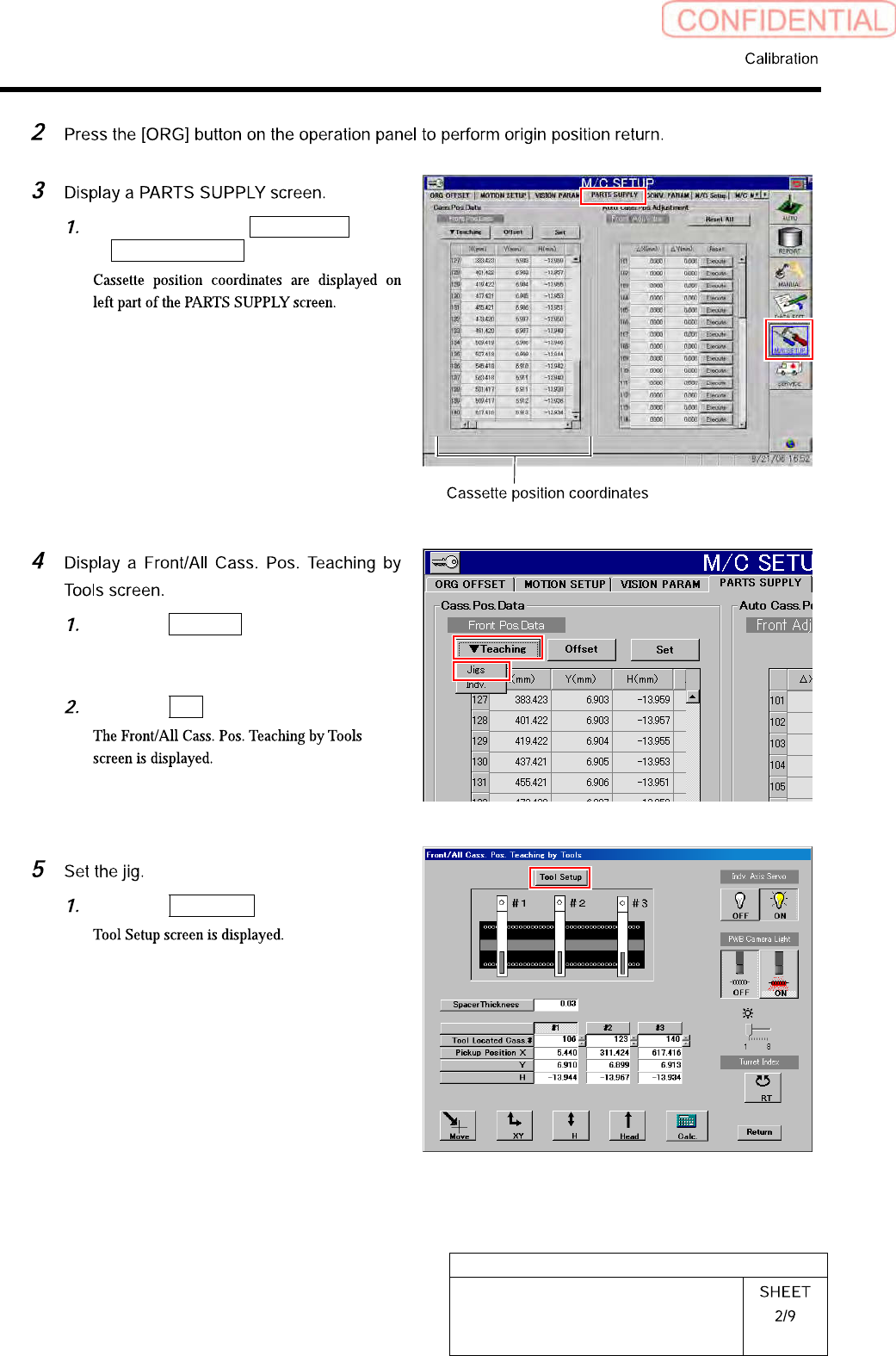
Click in an order of M/C SETUP menu
PARTS SUPPLY tab.
Click the Teaching button on the Front
Pos. Data to display a drop down
menu.
Click the Jigs in the drop down menu.
Click the Tool Setup button.
HLGB-10311-01
Pickup Position Setup
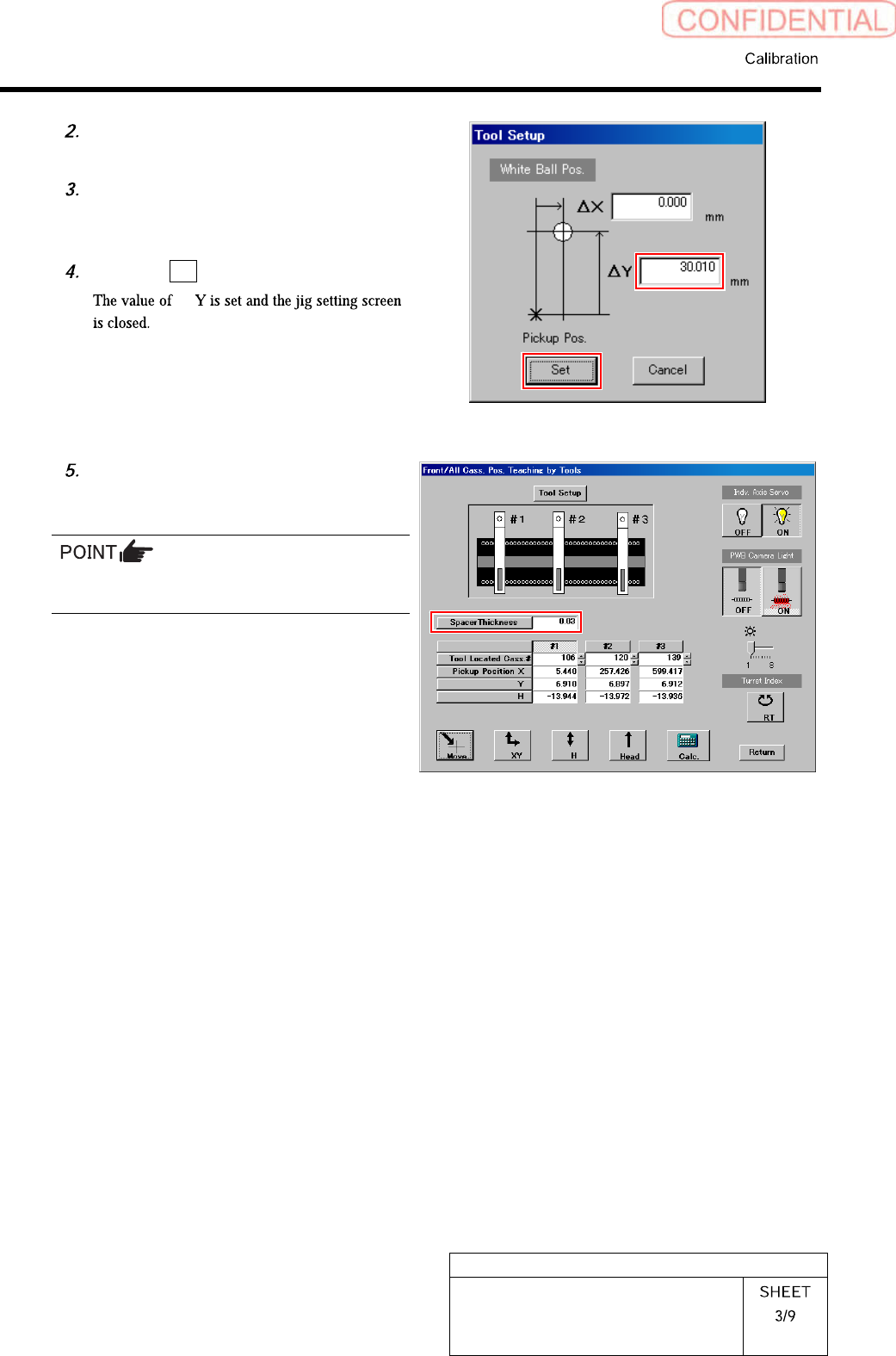
Check jig information (ΔY) attached
on the side of the pickup point jig.
Enter value ofΔY written on the side
of the pickup point jig into the ΔY box
on the jig setting screen.
Click the Set button.
Δ
Input thickness of “0.03” of thickness
gauge used for H axis position data
teaching.
The value of the spacer thickness becomes
offset value when acquiring H coordinate.
HLGB-10311-01
Pickup Position Setup
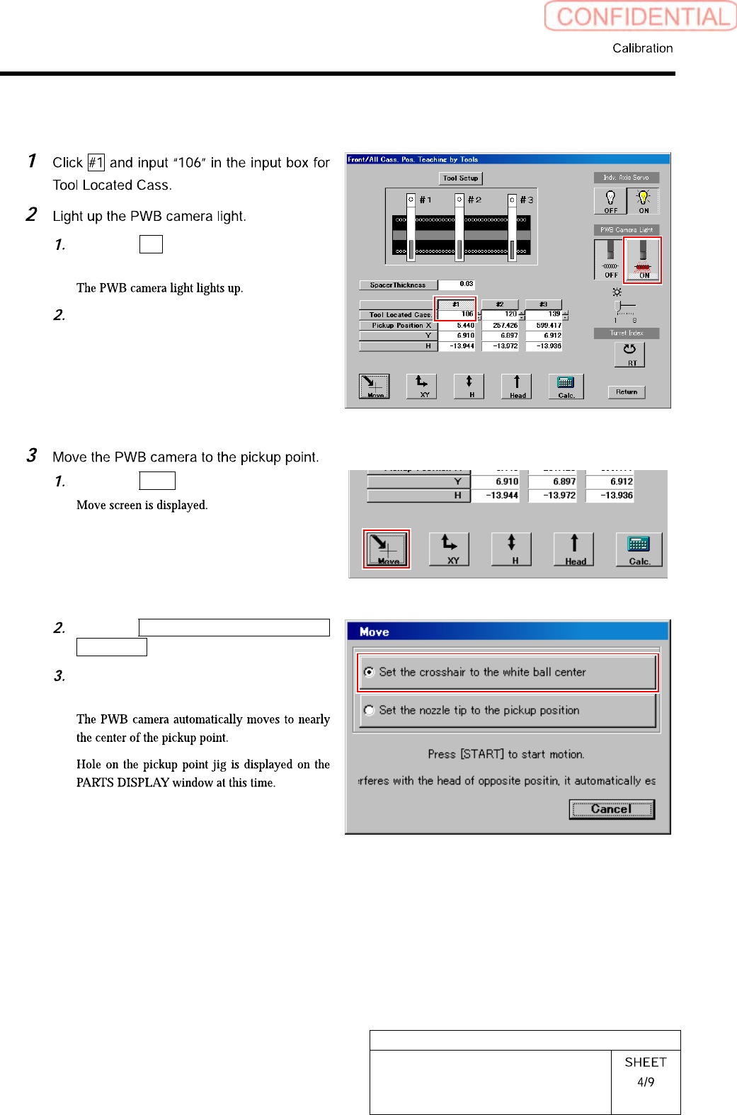
[XY Position Data Teaching]
Click the ON button on the PWB
camera light.
Set brightness of the PWB camera
light to “6” or “7”.
Click the Move button.
Click the Set the crosshair to the white
ball center button.
Press the [START] button on the
operation panel.