MAN00000772_SI-G200BB_SVCPDFA.pdf - 第329页
HLGB-10414-01 Phase A djustment for Nozzle Do not remove the set screw fixing the smal l gear . Otherwise, the set shoe may fall. T urn the emergency stop switch to release emer g ency stop. Click the [ORG] bu tto n t o …
HLGB-10414-01
Phase Adjustment for Nozzle
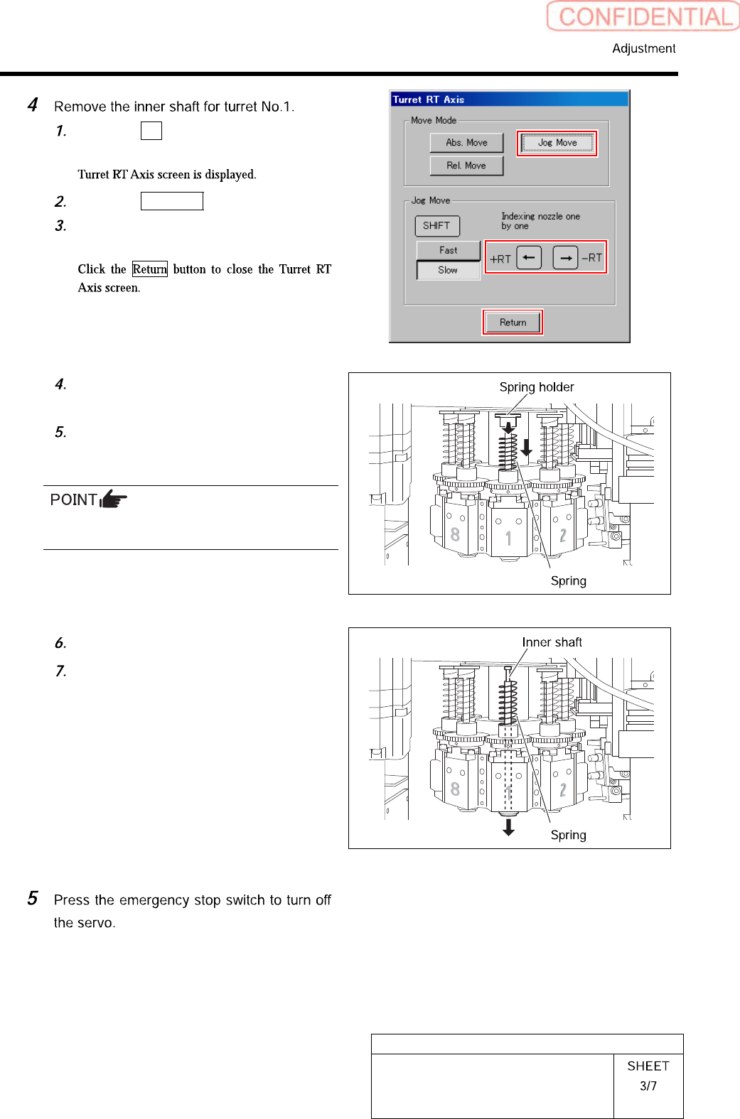
Click the RT button on the Axis
MOTION screen.
Click the Jog Move button.
Press the left and right cursor key to
move the turret No.1 to the front.
Turn the notch on the spring holder to
deep side.
Pull the spring holder toward you with
the spring being lowered down to
remove the spring holder.
Be careful to prevent the inner shaft from
falling.
Remove the spring.
Pull out the inner shaft from lower
side of the head.
HLGB-10414-01
Phase Adjustment for Nozzle
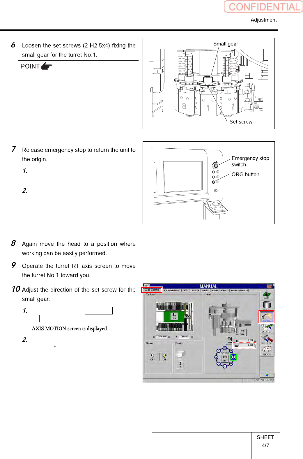
Do not remove the set screw fixing the small
gear. Otherwise, the set shoe may fall.
Turn the emergency stop switch to
release emergency stop.
Click the [ORG] button to return the
system to the original position.
Click in an order of MANUAL menu
AXIS MOTION tab.
Check that current position of the RN
axis is 0 .
HLGB-10414-01
Phase Adjustment for Nozzle
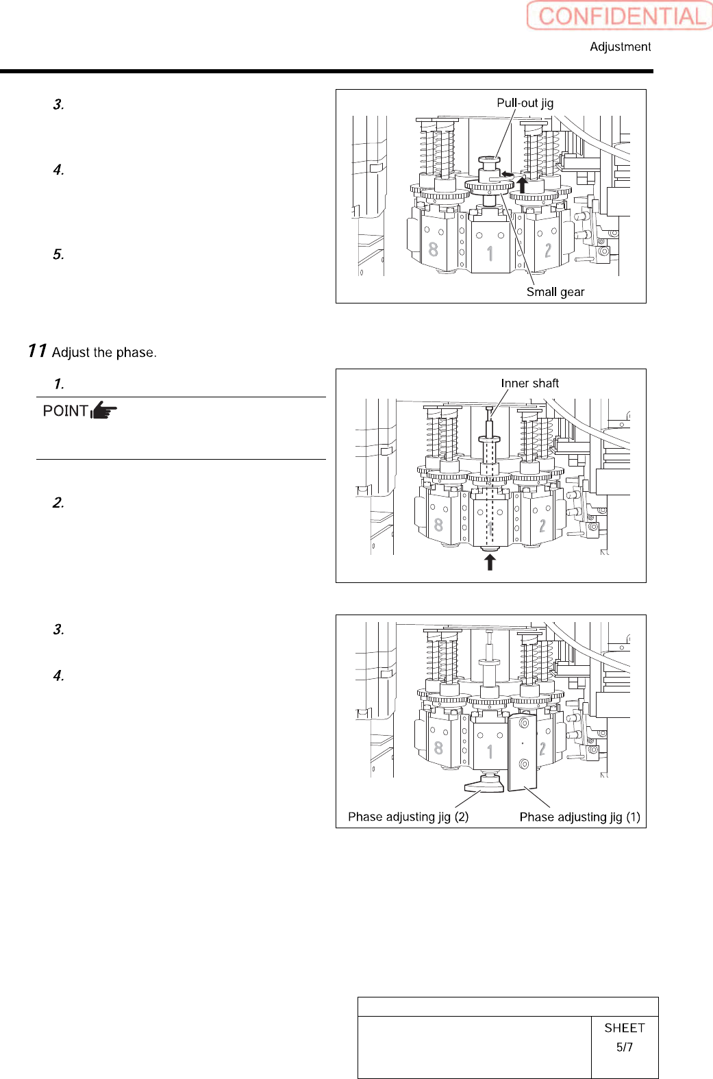
Put a pull-out jig on the upper part of
the spline nut and pull the small gear
quietly to move.
Change the direction of the small gear
so that position of the set screw on the
left of the small gear is on the front
toward you.
Quietly lower the small gear from the
pull-out jig and move it to the spline
nut.
Insert the inner shaft temporarily.
Pay attention to phases of the inner shaft and
the spline nut.
Turn the inner shaft so that the
marking (scribing line) on the inner
shaft is directed to the front.
Install a phase adjusting jig (1) with
cap screws (2-CP3x14).
Install the phase adjusting jig (2) at
the lower side of the inner shaft.