MAN00000772_SI-G200BB_SVCPDFA.pdf - 第71页
Install Tray Unit (Including machine modification) SHEET 32/73 WKGB-10104-03 Installing Tray Unit (Including machine modificat ion) 3 Install the shooter cover to the lower side of the cassette t able. 1. Fix the d…
Install Tray Unit (Including machine modification)
SHEET
31/73
WKGB-10104-03
Installing Tray Unit
(Including machine modification)
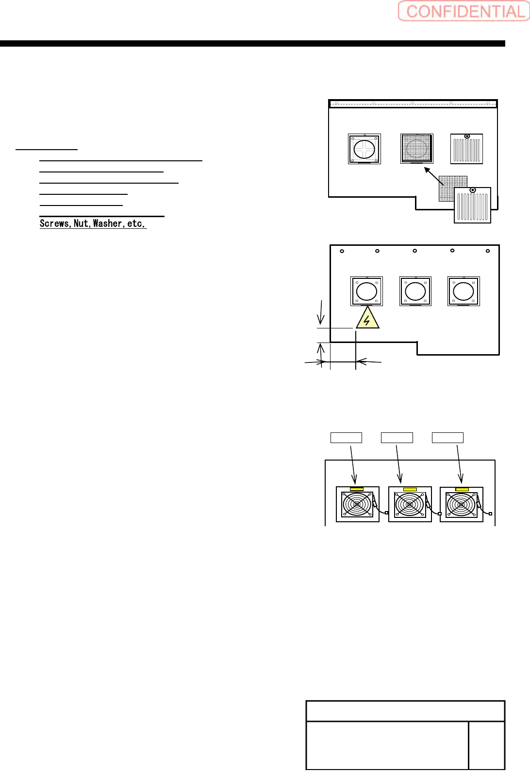
[Installation of rear center cover]
1
Import all parts to the tray center cover
from the existing center cover.
Re-use Parts:
HANDLE, ALUMINUM(3-218-296-02)
COVER, FAN(2-693-879-01)
GUARD, FILTER(2-889-206-01)
Filter(2-055-233-02)
FAN(1-763-987-11)
GUARD, FAN(4-720-311-01)
2
Stick lightning label, FAN-R1, FAN-R2
and FAN-R3 seals on the cover.
FAN-R1FAN-R2 FAN-R3
Cover reverse face
40[㎜]
20[㎜]
Cover obverse face
Install Tray Unit (Including machine modification)
SHEET
32/73
WKGB-10104-03
Installing Tray Unit
(Including machine modification)
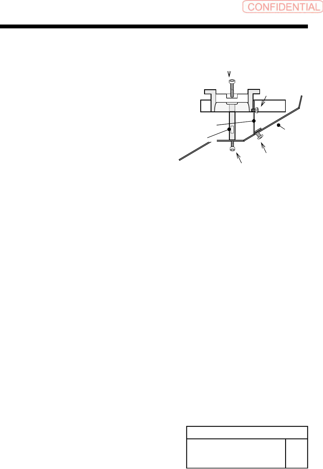
3
Install the shooter cover to the lower
side of the cassette table.
1.
Fix the discharge guide bracket to the discharge
cover with the 3-T4x6.
2.
Fix the discharge guide shaft to the discharge
cover with the 2-CP6x10.
3.
Fix the Discharge guide shaft to the lower side of
the cassette table with the 2-cp6x30.
Discharge cover
Discharge guide bracket
Discharge guide shaft
3-T4x6
2-CP6X30
3-CP4x6
2-CP6X10
Install Tray Unit (Including machine modification)
SHEET
33/73
WKGB-10104-03
Installing Tray Unit
(Including machine modification)
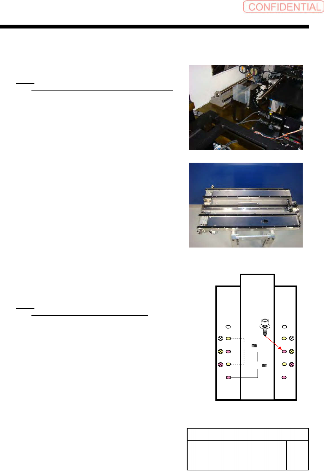
[Installation of S axis unit]
1
Remove the discard box.
NOTE:
The unit of tray specification essentially uses the
discard box.
2
Loosen the 8-+T4x8 on the upper
section of the S axis unit to remove the
cover.
3
Set to the position of the parallel pin on
the cassette table and place the S axis
unit on the cassette table.
NOTE:
Be careful not collide to the fixed camera.
4
Fix the S axis unit with the 4-CP6x20.
5
Install the cover using the 8-+T4x8.
410
360