MAN00000772_SI-G200BB_SVCPDFA.pdf - 第188页
HLGB-10206-01 F A xis Setup Perform this working on r e spective F a xis on the front side and rear side. [Necessary jigs] • Fe ed adjusting jig • Part fe ed h ei ght ji g • Thickness gauge [Procedure] Set the replacing …
HLGB-10205-01
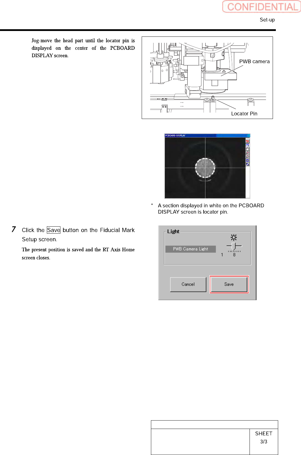
Fiducial Mark Setup
HLGB-10206-01
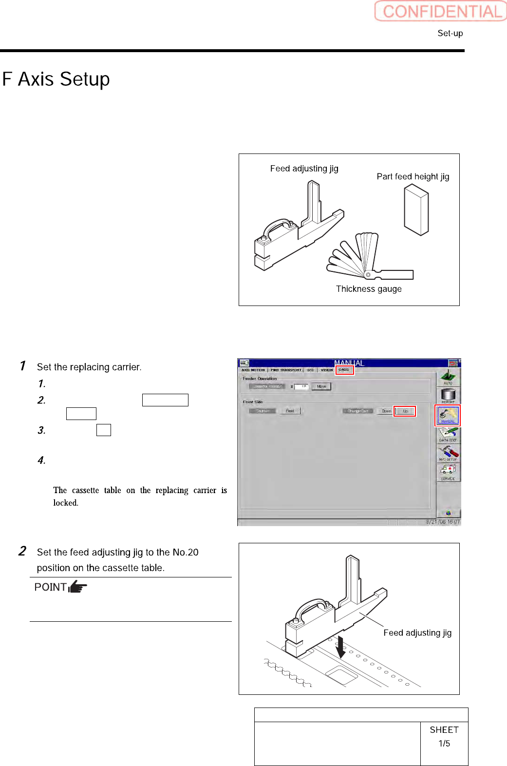
F Axis Setup
Perform this working on respective F axis on the front side and rear side.
[Necessary jigs]
• Feed adjusting jig
• Part feed height jig
• Thickness gauge
[Procedure]
Set the replacing carrier on the unit.
Click in an order of MANUAL menu
CASS. tab.
Click the Up button for the replacing
carrier on the front or rear side.
Press the [START] button on the
operation panel.
There should be no gap between the feed
adjusting jig and the cassette table.
HLGB-10206-01
F Axis Setup
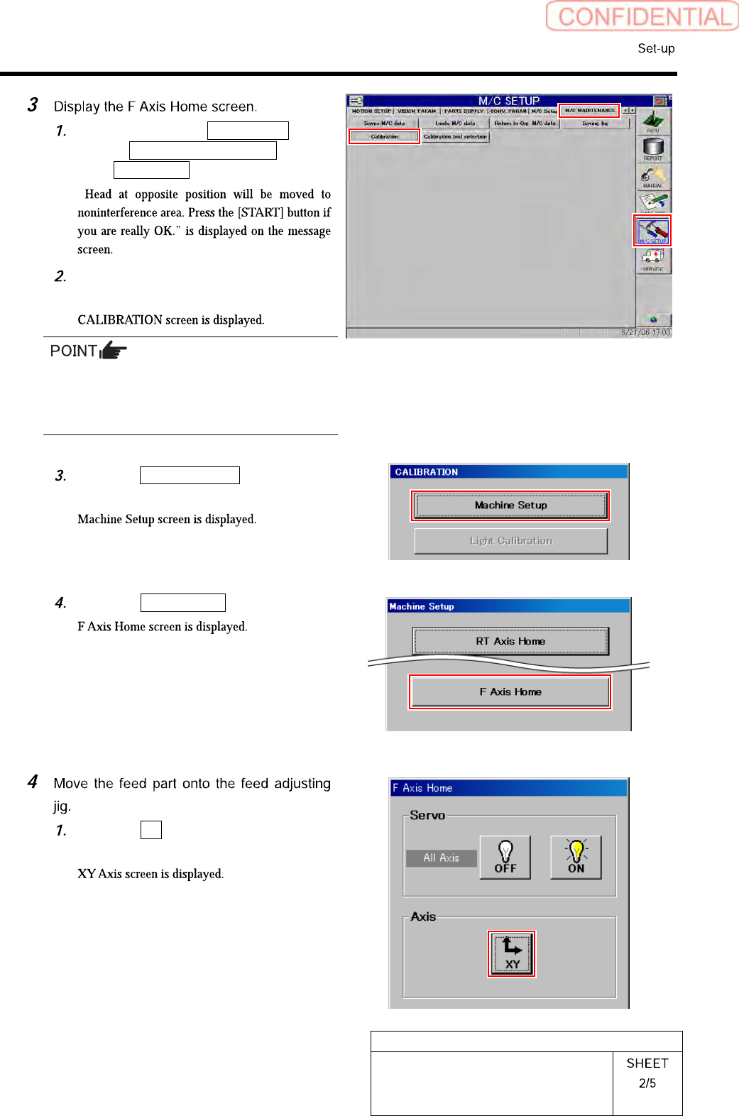
Click in an order of M/C SETUP
menuM/C MAINTENANCE
tabCalibration button.
“
Press the [START] button on the
operation panel.
For procedures when selecting head for which
calibration is performed, and when changing
calibration jig, refer to the “How to display
calibration screen (HLGB-10105-01)”.
Click the Machine Setup button on the
CALIBRATION screen.
Click the F Axis Home button.
Click the XY button on the F Axis
Home screen.