MAN00000772_SI-G200BB_SVCPDFA.pdf - 第338页
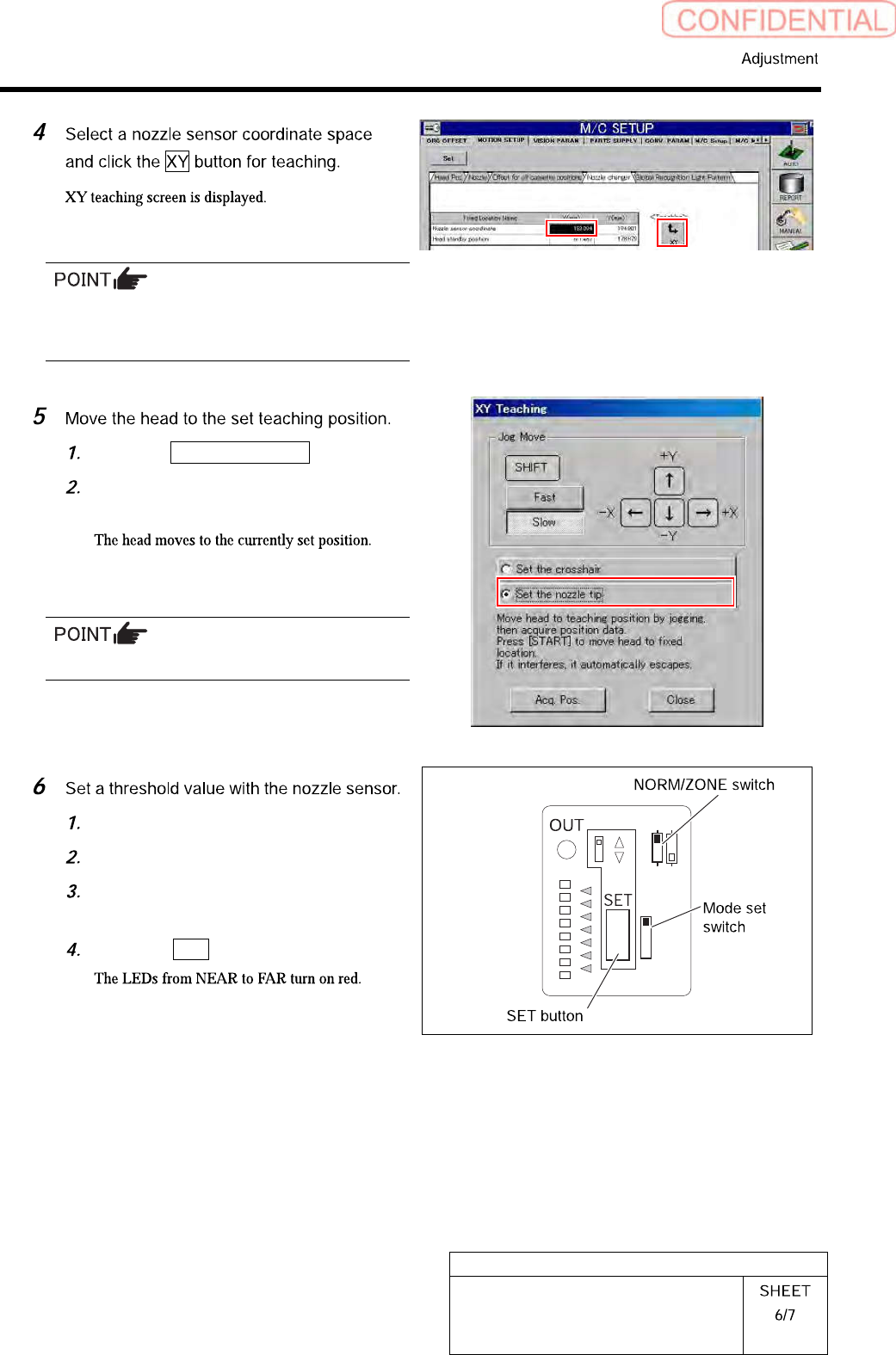
HLGB-10415-01 Nozzle Sensor A djustment If the T e achin g button does not become enabled, click on th e “Nozzle sensor coordina te ” column and then click the T eaching button again. Click the Set the nozzle tip button.…
HLGB-10415-01
Nozzle Sensor Adjustment
[Threshold value setting for sensor]
Set the threshold value after the XY coordinate for the nozzle has been set.
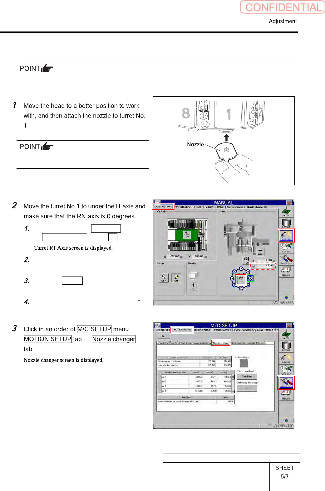
Attach the nozzle used in the production process
(do not attach the jig nozzle).
Click in an order of MANUAL menu
AXIS MOTION tab RT button.
Operate the RT axis screen and move
the turret No.1 down to the H axis.
Click the Return button to close the
Turret RT Axis screen.
Check that angle of the RN axis is 0
on the axis operation screen.
HLGB-10415-01
Nozzle Sensor Adjustment
If the Teaching button does not become enabled,
click on the “Nozzle sensor coordinate” column
and then click the Teaching button again.
Click the Set the nozzle tip button.
Press the [START] button on the
operation panel.
Do not click the Acq. Pos. button.
Open the sensor cover.
Set the mode set switch to TEACH.
Check that the NORM/ZONE switch is
set to NORM.
Press the SET button.
NORM
TEACH
RUN
ADJ
ZONE
L
D
NEAR
FAR
HLGB-10415-01
Nozzle Sensor Adjustment
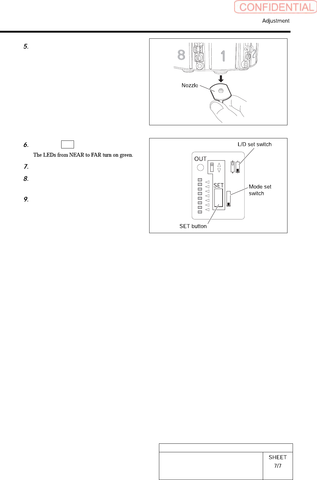
Remove the nozzle for production
installed on the turret No. 1.
Press the SET button again.
Set the mode set switch to RUN.
Check that the L/D set switch is set to
the D side.
Close the cover for the sensor.
NORM
TEACH
RUN
ADJ
ZONE
L
D
NEAR
FAR