MAN00000772_SI-G200BB_SVCPDFA.pdf - 第341页
HLGB-10417-01 Adjustment of Cassette Float Sensor Height This sect i on d escribes a procedure to adjust the height of the cassette float sensor by using feed adjusting jig and casse tte float sensor height adjusting jig…
HLGB-10416-01
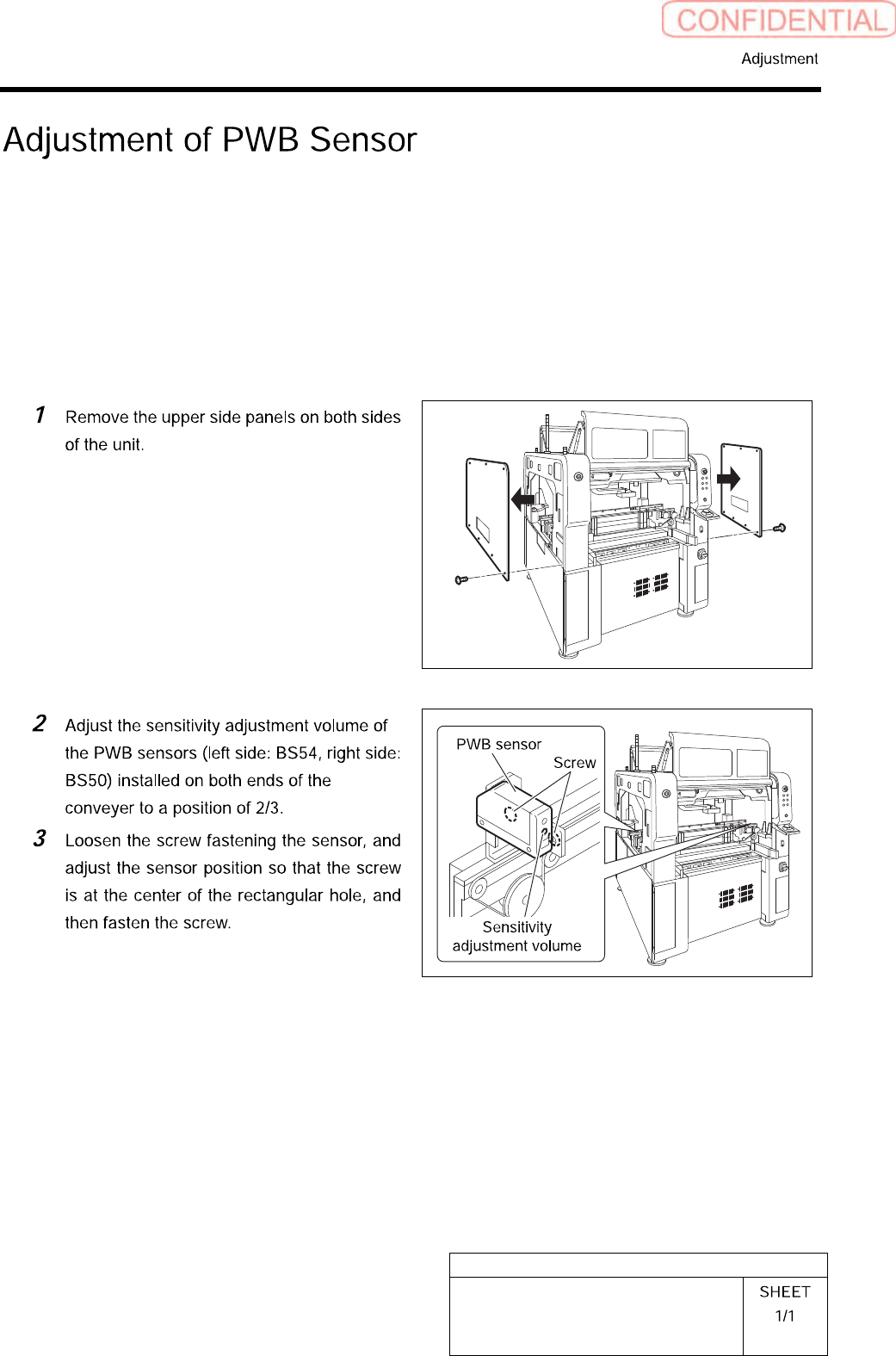
Adjustment of PWB Sensor
This section describes a procedure to adjust sensitivity and installing position of PWB detecting
sensor (BS54, BS50).
[Necessary jigs]
• Do not Use jig.
[Procedure]
HLGB-10417-01
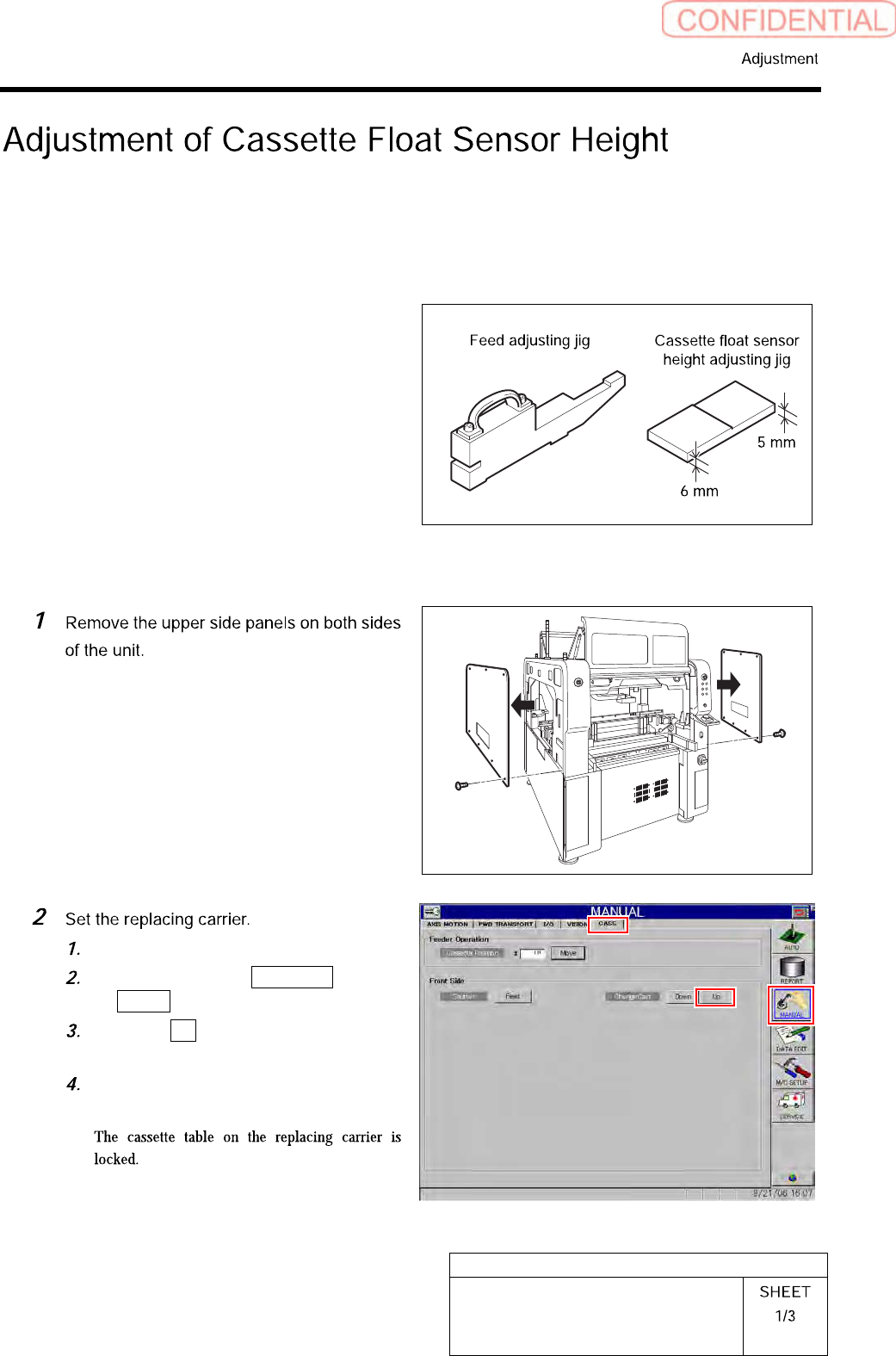
Adjustment of Cassette Float Sensor
Height
This section describes a procedure to adjust the height of the cassette float sensor by using feed
adjusting jig and cassette float sensor height adjusting jig.
[Necessary jigs]
• Feed adjusting Jig
• Cassette float sensor height adjusting Jig
[Procedure]
Set the replacing carrier on the unit.
Click in an order of MANUAL menu
CASS. tab.
Click the Up button for the replacing
carrier on the front or rear side.
Press the [START] button on the
operation panel.
HLGB-10417-01
Adjustment of Cassette Float Sensor
Height
Check that there’s no gap between the
cassette table and support column
mounting face.
Thickness gauge of t=0.02should not be
inserted between the mounting faces.
Loosen the cap screws (2-M4) on the
attachment bracket for the cassette
float sensors (left side: BS-63R, right
side: BS-63T) installed in the vertical
frame of the base stand.
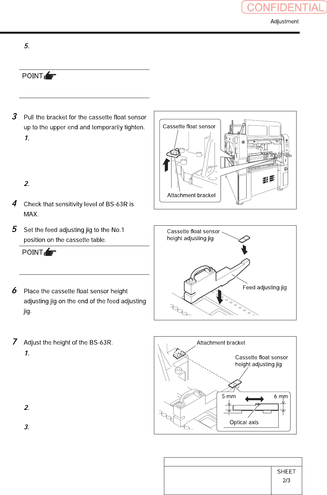
Pull the bracket up to the upper end
and temporarily fasten.
There should be no gap between the feed
adjusting jig and the cassette table.
Adjust the BS-63R attachment bracket
position so that the LED for the
BS-63R lights up at a part of 5 mm on
the cassette float sensor height
adjusting jig, and the LED
extinguishes at a part of 6 mm.
Fasten the cap screw to fix the
attachment bracket.
Again, move the cassette float sensor
height adjusting jig back and forth to
check that the LED turns ON/OFF well.