MAN00000772_SI-G200BB_SVCPDFA.pdf - 第607页
BBGB-10101-01 A larm List for the Servo Pack "Sigma-III" Series (SGDS type) Switching Mode Connect the digital operator to the SERVOP ACK, and t urn ON the power to the SERVOP ACK. The init ial display appears,…
BBGB-10101-01
Alarm List for the Servo Pack
"Sigma-III" Series (SGDS type)
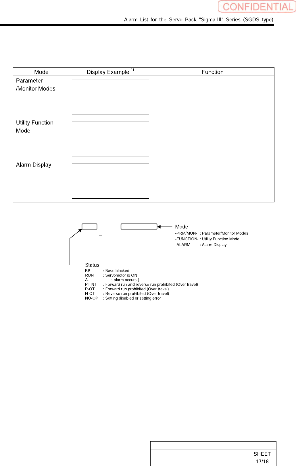
Mode Selection
The digital operator has four display modes:
BB -PRM/MON-
Un000= 00000
Un002= 00000
Un008= 00000
Un00D=00000000
Displays the monitor item Un.
Displays and set a parameter Pn.
BB -FUNCTION-
Fn00E
Fn000
Fn001
Fn002
Executes a utility function Fn.
*2
BB -ALARM-
0:D00 00001207196
1:720 00000032651
2:511 00000009043
3:---
Displays the alarm traceback data.
The latest 10 alarms are displayed with type
stamp.
*1
The abbreviation of each mode is displayed on the right top, and the SERVOPACK status is displayed
on the left top.
BB -PRM/MON-
Un000= 00000
Un002= 00000
Un008= 00000
Un00D=00000000
*** : Th ***: Alarm code)
*2 Utility Function Fn
• Alarm traceback data display
• JOG mode operation
• Program JOG operation
• Clear alarm traceback data
• Absolute encoder multi-turn reset and encoder
alarm reset
• Manual zero adjustment/Manual gain
adjustment of analog monitor output
• Write prohibited setting
• Software version display
• One-parameter autotuning for less deviation
• One-parameter autotuning
• Online vibration monitor
• SERVOPACK and servomotor ID display
• Rigidity setting during normal autotuning
• Origin search mode
• Initialize parameter settings
• Save moment of inertia ratio data obtained from
normal autotuning
• Automatic/Manual adjustment of analog
reference offset
• Automatic/Manual offset-adjustment of motor
current detection signal
• Check servomotor models
• Multi-turn limit value setting change when a
Multi-turn Limit Disagreement alarm occurs
• Advanced autotuning
• EasyFFT
• Initialize vibration detection level
BBGB-10101-01
Alarm List for the Servo Pack
"Sigma-III" Series (SGDS type)
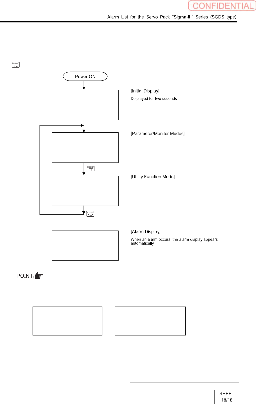
Switching Mode
Connect the digital operator to the SERVOPACK, and turn ON the power to the SERVOPACK.
The initial display appears, and then the Parameter/Monitor Mode display appears. Press the
Key to change the mode. When an alarm occurs, the alarm display appears automatically.
File list loading
Please wait….
BB -PRM/MON-
Un000= 00000
Un002= 00000
Un008= 00000
Un00D=00000000
BB -FUNCTION-
Fn01E
Fn000
Fn001
Fn002
A.D00 -ALARM-
0:D00 00001207196
1:720 00000032651
2:511 00000009043
3:---
If a communications error occurs between the SERVOPACK and digital operator, the following
communications error codes are displayed. These errors may be caused by incorrect connector
connection. Check the connection and correct. Then, turn the power OFF and ON. If the error
still occurs, replace the digital operator or the SERVOPACK.
CPF00
COM-ERR(OP&SV)
CPF01
COM-ERR(OP&SV)
* For detail of how to operate Digital Operator, refer to the “Instruction Manual for Sigma-III
Series SGMS/SGDS Digital Operator” in separate volume.
BBGB-10102-01
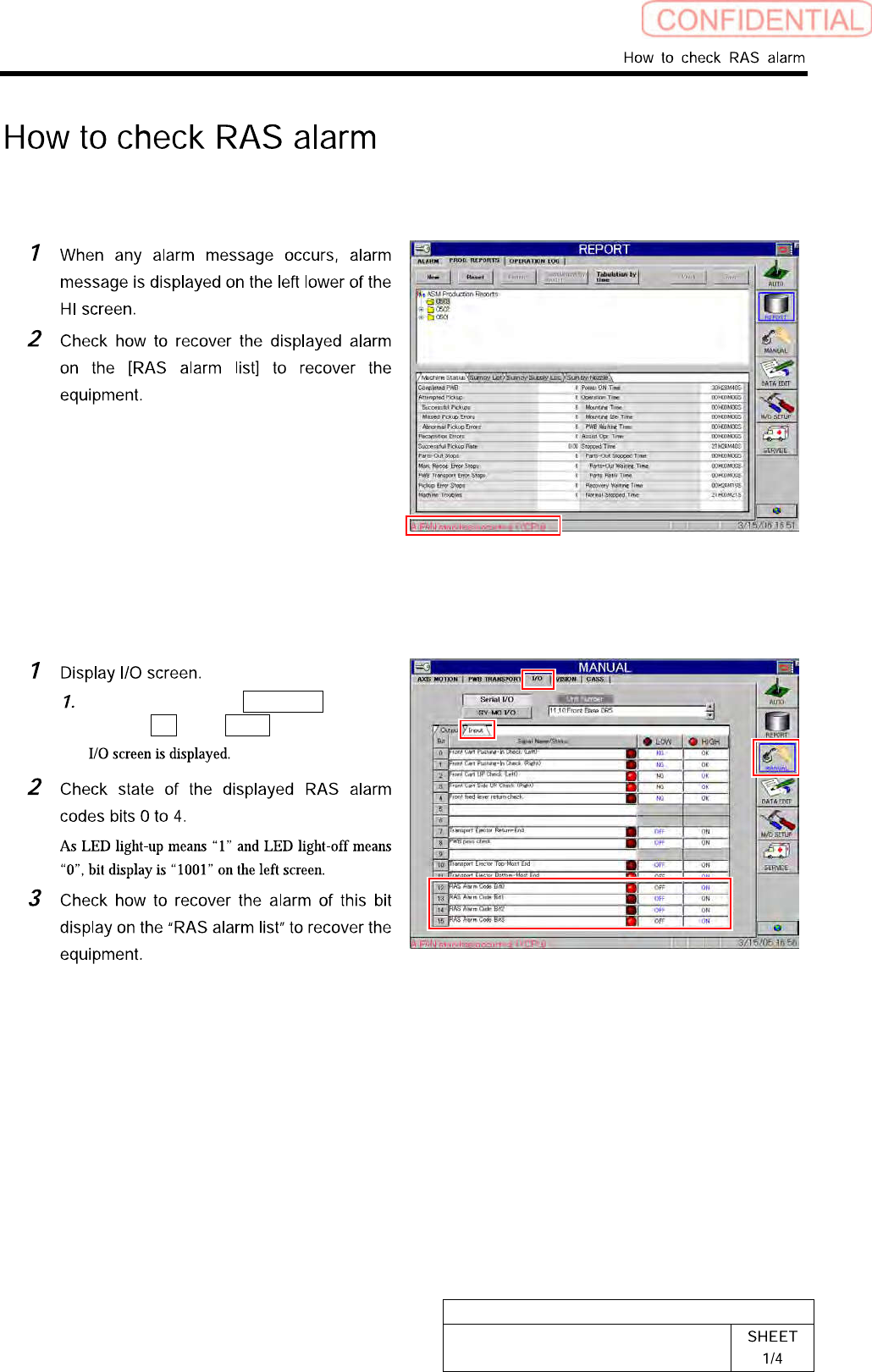
How to check RAS alarm
[Checking procedure on HI screen (alarm message)]
[Checking procedure on HI screen (bit display)]
Click in an order of MANUAL
menuI/O tabInput tab.