MAN00000772_SI-G200BB_SVCPDFA.pdf - 第16页
WKGB-10102-01 G200BB Head Maintenance T urn off the V ACUUM b reaker on the power unit part. Click in an ord er of MANUAL menu AXIS M OTION tab XY button. Click the Jog Move button. Press the cursor key to move th e …
WKGB-10102-01
G200BB Head Maintenance
This document explains the G200BB head maintenance procedure.
Follow the same procedure to perform maintenance on the front head and rear head.
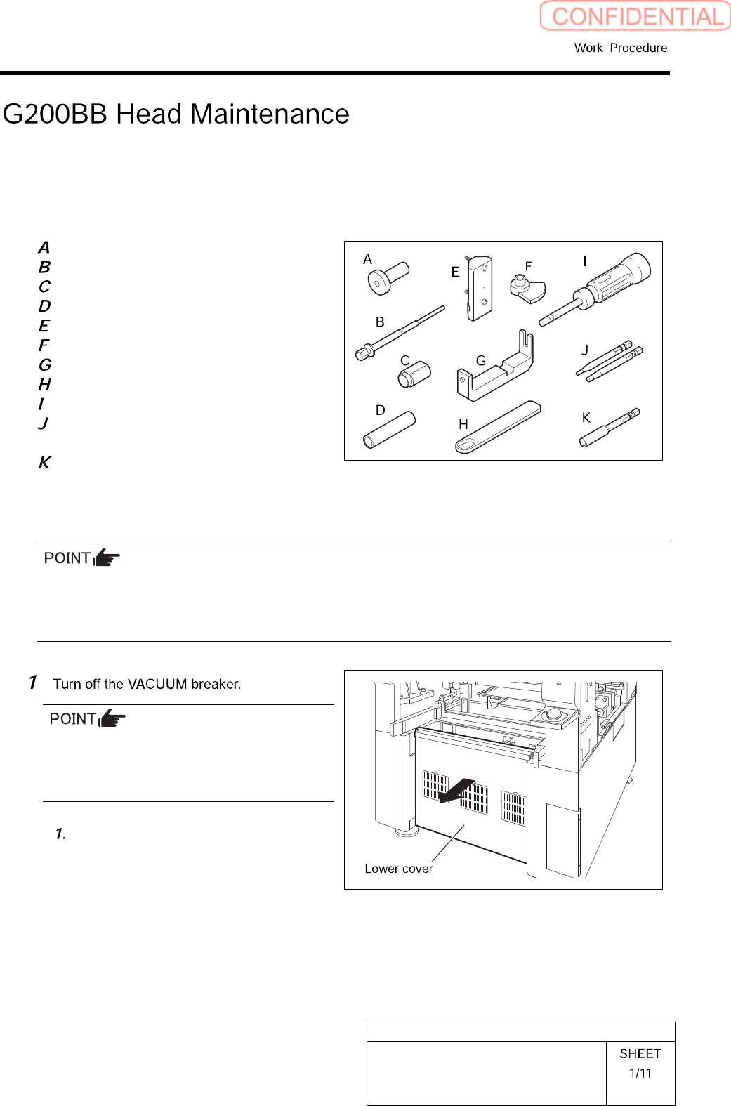
[Necessary jigs]
Pulling jig
Spline nut assembling jig (1)
Spline nut assembling jig (2)
Bearing press fitting jig
Gear phase adjustment jig (1)
Gear phase adjustment jig (2)
Spring holding hook
Spacer assy retainer
Torque screwdriver
(6[cN•m] to 40 [cN•m])
Bit for torque screwdriver
(1.27 [mm], 2.5 [mm])
Bit for air screwdriver
(width across flats: .5 mm)
[Disassembling Procedure]
To assure the mounting accuracy, the inner shaft is strictly paired with the ball bush guide unit and the
collar when the system is manufactured. In order not mix the disassembled parts with those for other
Indexes, control the parts separately by each Index. When reassembling, assemble the original parts and
attach them to the original index.
Turn OFF the VACUUM breaker before
removing the mechanical valve in order to
prevent suction of contaminant and dust from
the mechanical valve.
Loosen the screws (2-+T4×8) to
remove the lower cover on the back of
the unit.
WKGB-10102-01
G200BB Head Maintenance
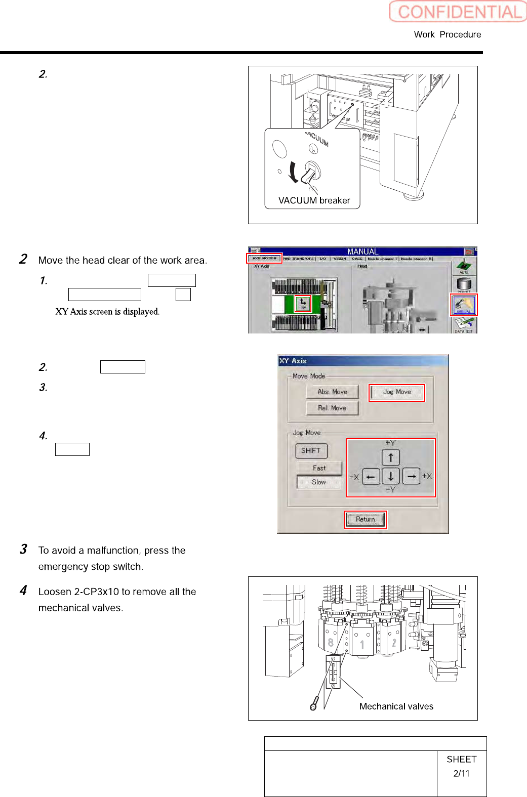
Turn off the VACUUM breaker on the
power unit part.
Click in an order of MANUAL menu
AXIS MOTION tab XY button.
Click the Jog Move button.
Press the cursor key to move the head
to a position where working is easily
performed.
After moving the head, click the
Return button to close the XY Axis
screen.
WKGB-10102-01
G200BB Head Maintenance
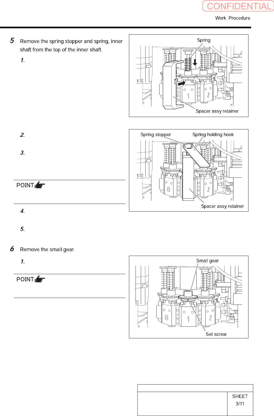
Hold the spring on the upper parts of
the inner shaft to install the spacer.
Direction the notch parts of the spring
stopper to the deep side.
Hang the spring holding hook, and
draw the spring stopper toward you to
remove. The spring stopper can be
removed by hand.
Be careful to prevent the inner shaft from
falling.
Remove the spring stopper and the
spring.
Pull out the inner shaft from lower
side of the head.
Loosen the set screws (2-H2.5x4)
fixing the small gear.
Do not remove the set screw fixing the small
gear. Otherwise, the set shoe may fall.