MAN00000772_SI-G200BB_SVCPDFA.pdf - 第325页
HLGB-10413-01 Nozzle Escape Detect Sensor Position Adjustment On the RN / H Axis screen, click check box for H axis and put check in it to input “-1.5”. Press the [ST ART] butto n on the operation panel. Check that the s…
HLGB-10413-01
Nozzle Escape Detect Sensor
Position Adjustment
L
SET RUN
UP DOWN MODE
D
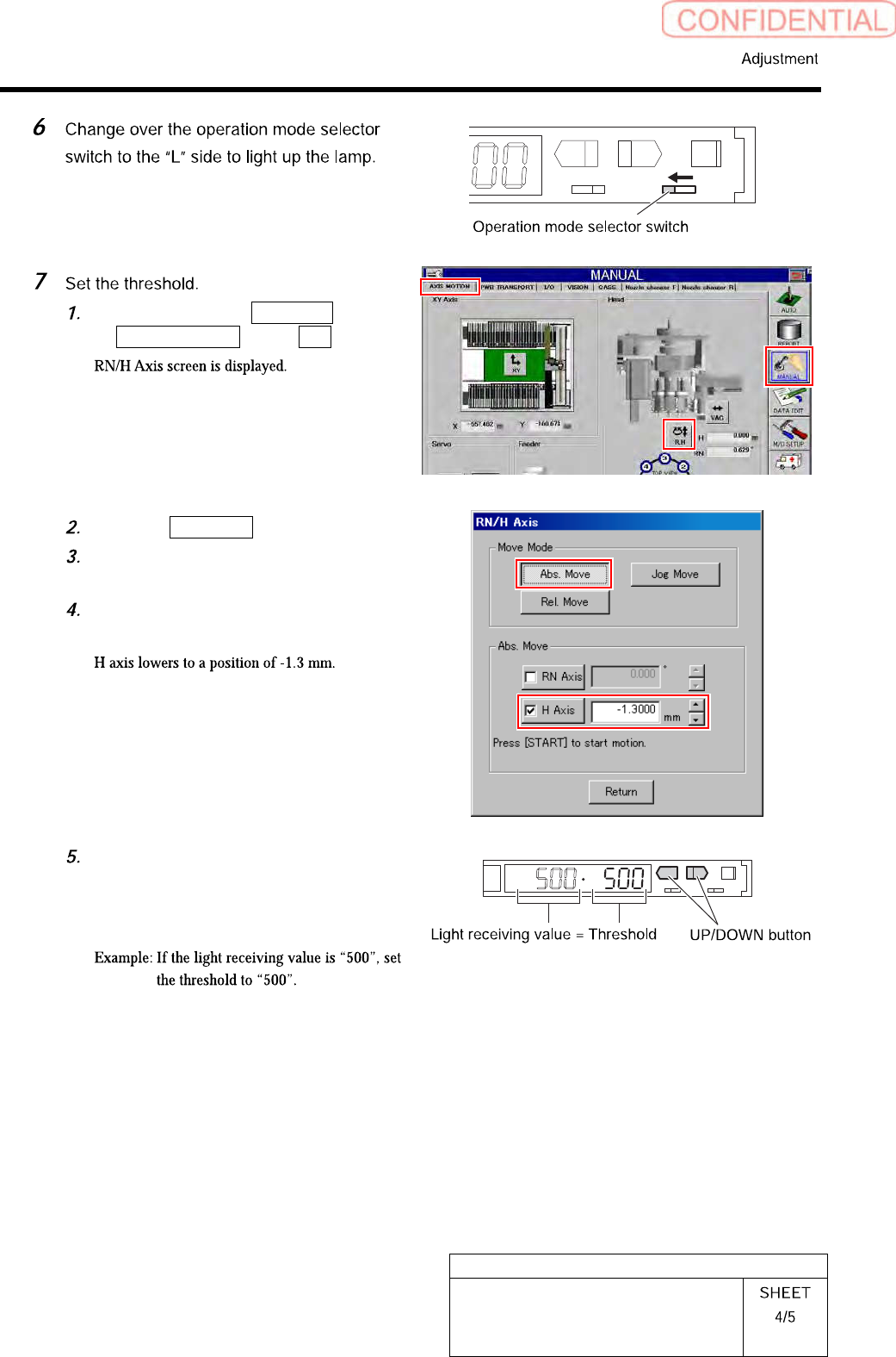
Click in an order of MANUAL menu
AXIS MOTION tab R.H button.
Click the Abs. Move button.
Click the check box for H axis and put
check in it to input “-1.3”.
Press the [START] button on the
operation panel.
Check the present light receiving
value with the nozzle omission
detection sensor amplifier, and set its
value to the threshold.
HLGB-10413-01
Nozzle Escape Detect Sensor
Position Adjustment
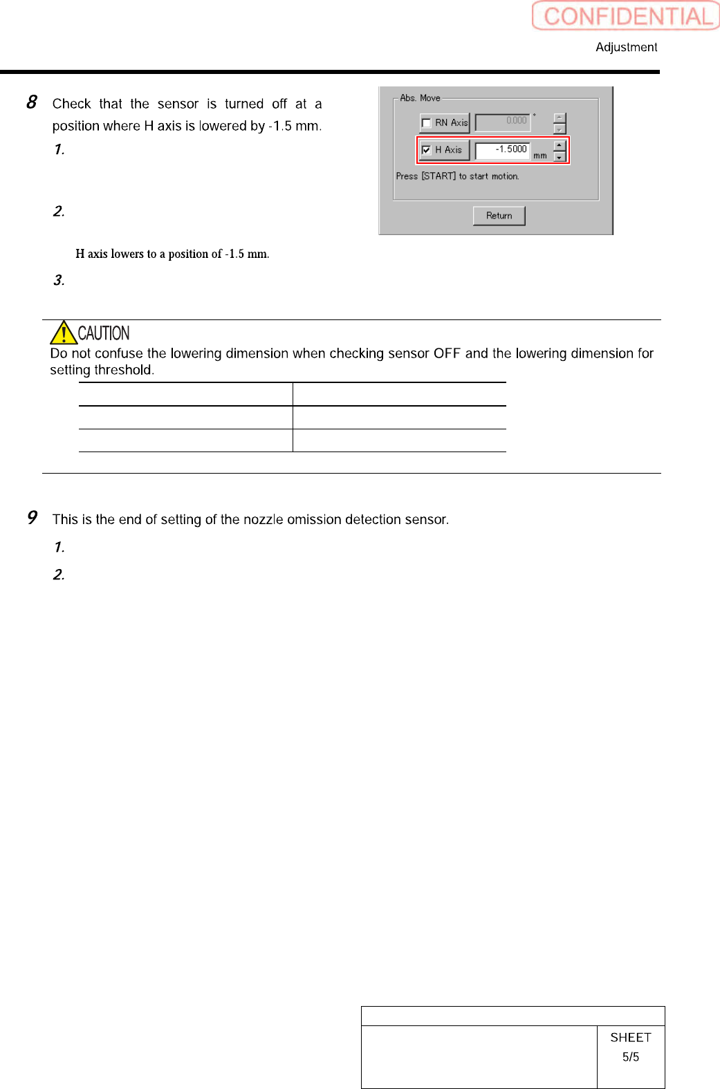
On the RN/H Axis screen, click check
box for H axis and put check in it to
input “-1.5”.
Press the [START] button on the
operation panel.
Check that the sensor is turned off.
Item H Axis lowering dimension
Threshold setting -1.3 mm
Sensor OFF check -1.5 mm
Close the cover for the nozzle omission detection sensor amplifier.
Remove the nozzle for production installed on the head.
HLGB-10414-01
Phase Adjustment for Nozzle
Perform this working on both heads on the front side and rear side.
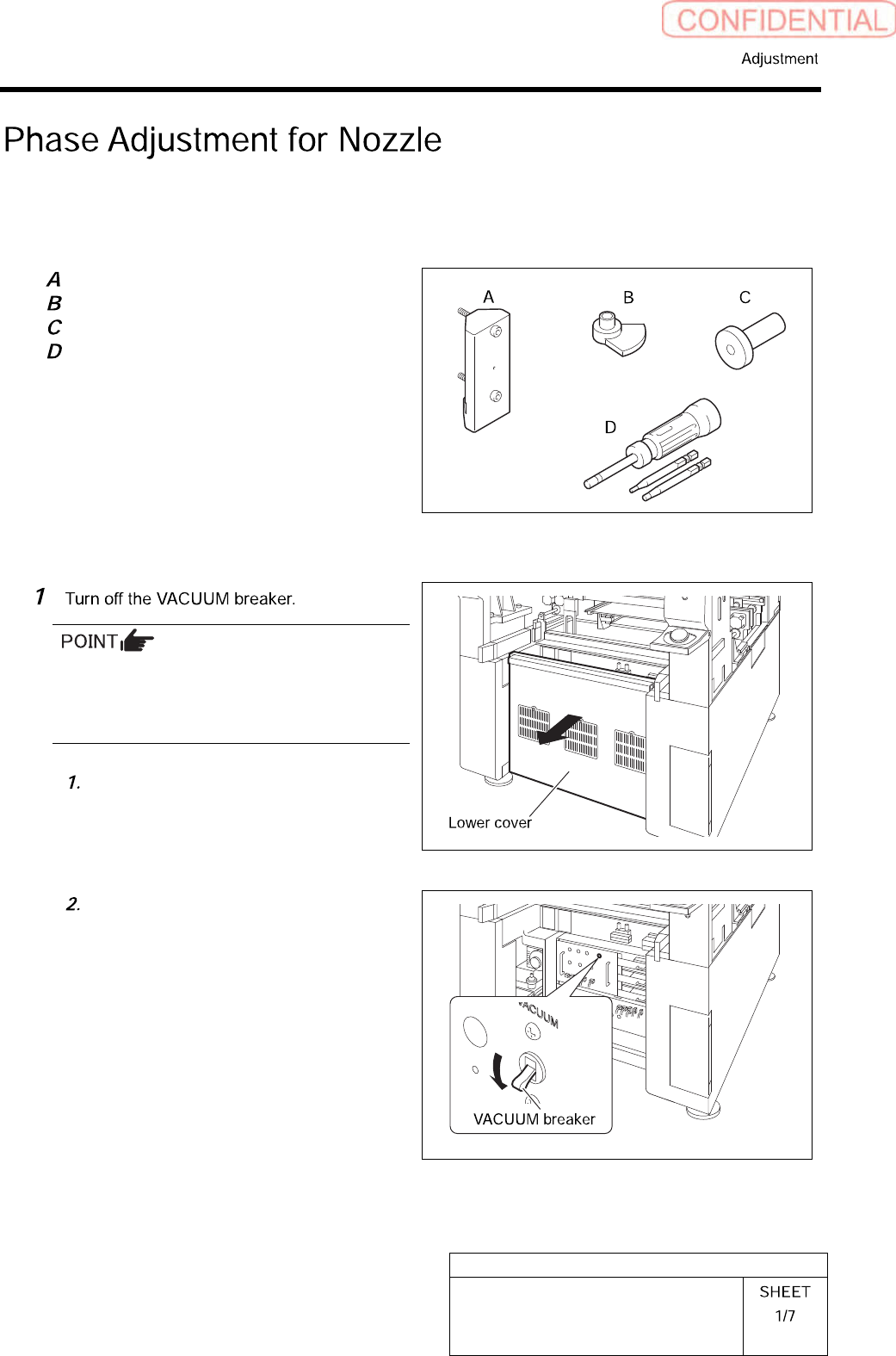
[Necessary jigs]
Phase adjusting jig (1)
Phase adjusting jig (2)
Pull-out jig
Torque driver (15[cN・m]~40[cN・m])
[Procedure]
Turn OFF the VACUUM breaker before
removing the mechanical valve in order to
prevent suction of contaminant and dust from
the mechanical valve.
Loosen the screws (2-+T4×8) to
remove the lower cover on the back of
the unit.
Turn off the VACUUM breaker on the
power unit part.