MAN00000772_SI-G200BB_SVCPDFA.pdf - 第313页
HLGB-10410-01 Gap A djustment for Head Unit Mechanical V alve and Plunger Perform this working on b o th he ads on t he front side and rear side. [Necessary jigs] • Thickness gauge (t=1.5 mm) [Prep aration before w ork ]…
HLGB-10409-01
Adjustment of RNF/RNR Axis Belt
Tension
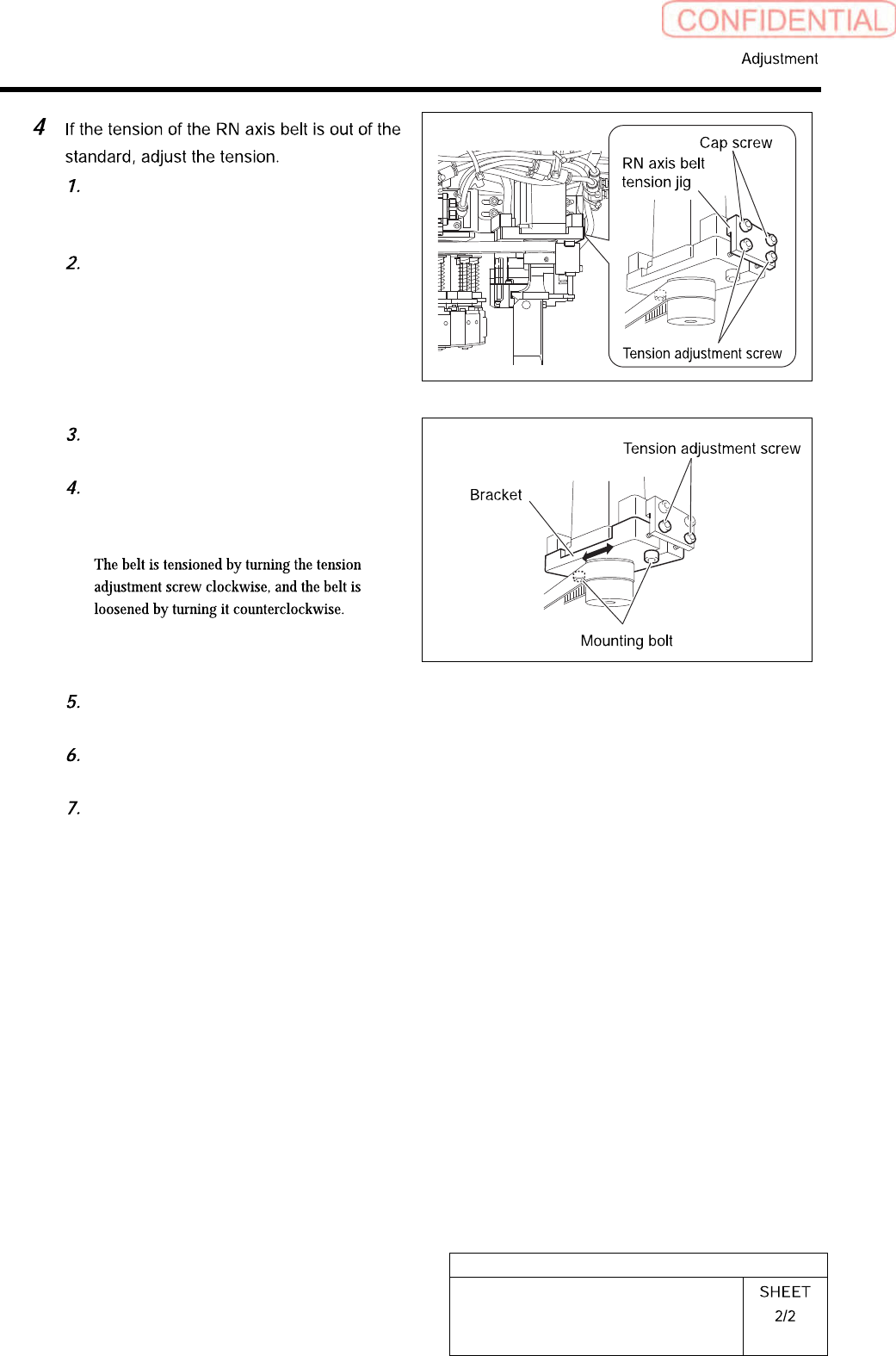
Install the RN axis belt tension jig to
the RN axis motor bracket with cap
screws (2).
Tighten the tension adjustment screw
into the motor bracket.
Loosen the RN axis motor bracket
mounting bolt.
Turn the tension adjustment screw for
the RN axis belt to adjust the belt
tension.
Measure the tension on the 4 locations on the RN axis belt by using tension meter to check
that the tension is within the standard.
After adjusting the tension, fasten the RN axis motor mounting bolt with a torque of 441
cN・m.
Remove the RN axis belt tension jig.
HLGB-10410-01
Gap Adjustment for Head Unit
Mechanical Valve and Plunger
Perform this working on both heads on the front side and rear side.
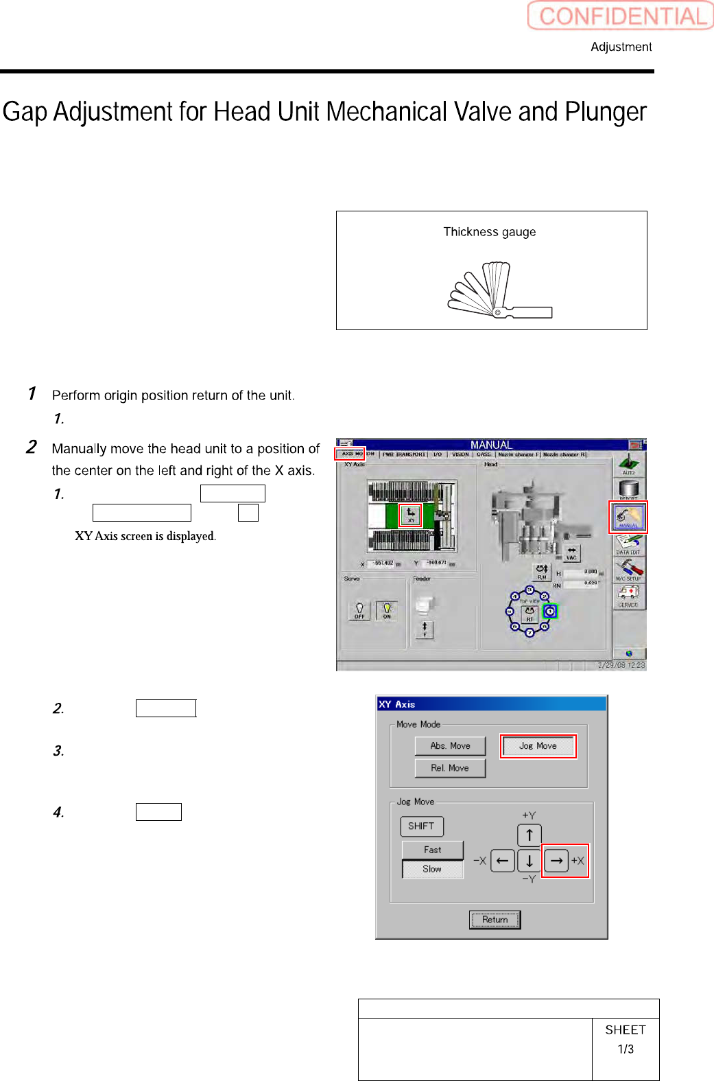
[Necessary jigs]
• Thickness gauge (t=1.5 mm)
[Preparation before work]
Press the [ORG] button on the operation panel with the HI screen being displayed.
Click in an order of MANUAL menu
AXIS MOTION tab XY button.
Click the Jog Move button in the move
mode.
Press the right cursor key to jog move
the head unit to the center position on
the left and right.
Click the Return button to close the
XY Axis screen.
HLGB-10410-01
Gap Adjustment for Head Unit
Mechanical Valve and Plunger
Because working has to be performed from the rear side of the head part, work on the head on the front
side from the rear of the unit, and the head on the rear side from the front of the unit.
Press the emergency stop switch on the working side to turn OFF the servo in order to prevent the unit
from being operated mistakenly from opposite side of the unit without noticing that the other worker is
working.
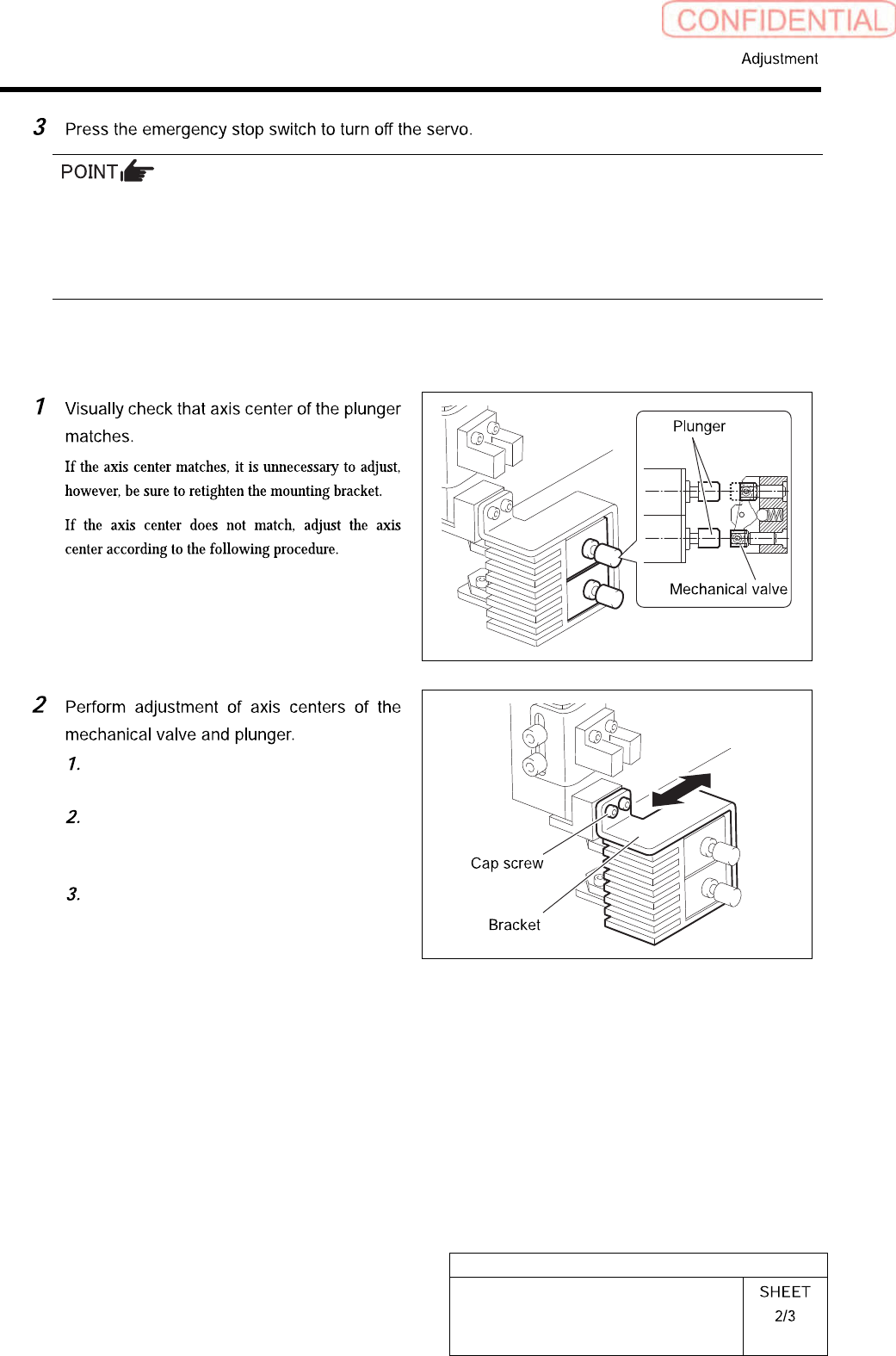
[Axis center adjuting procedure]
Loosen the cap screws (2 pcs, C3 x 6)
on the mounting bracket for plunger.
Move the bracket back and forth to
match the axis centers of the
mechanical valve and the plunger.
While matching the axis center in
height direction, fasten the cap screws
(2 pcs, C3 x 6) to fix the bracket.