MAN00000772_SI-G200BB_SVCPDFA.pdf - 第198页
HLGB-10208-01 Pickup Check Camera Setup × Before tightening cap screws (4-CP2.5 × 6), apply small amount of adhesive “1401B” of THREE BOND to prevent looseness. [Position adjustment for lowerin g end stopper] Click in an…
HLGB-10208-01
Pickup Check Camera Setup
Perform this working on both heads on the front side and rear side.
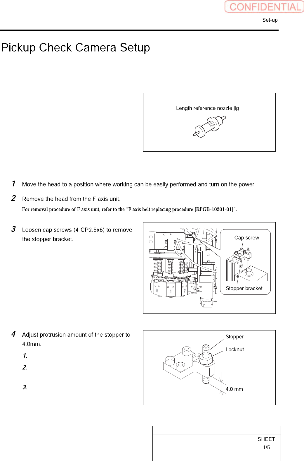
[Necessary jigs]
• Length reference nozzle jig
• Scale (about 150 mm)
[Position adjustment for rise end stopper]
Loosen the locknut.
Adjust protrusion amount of the
stopper to 4.0mm.
Tighten the locknut.
HLGB-10208-01
Pickup Check Camera Setup
×
Before tightening cap screws (4-CP2.5×6),
apply small amount of adhesive “1401B” of
THREE BOND to prevent looseness.
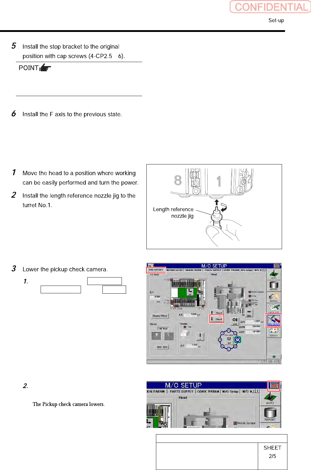
[Position adjustment for lowering end stopper]
Click in an order of M/C SETUP menu
ORG OFFSET tab ↓Check
button.
Press the arrow mark on the right
upper section of the screen.
HLGB-10208-01
Pickup Check Camera Setup
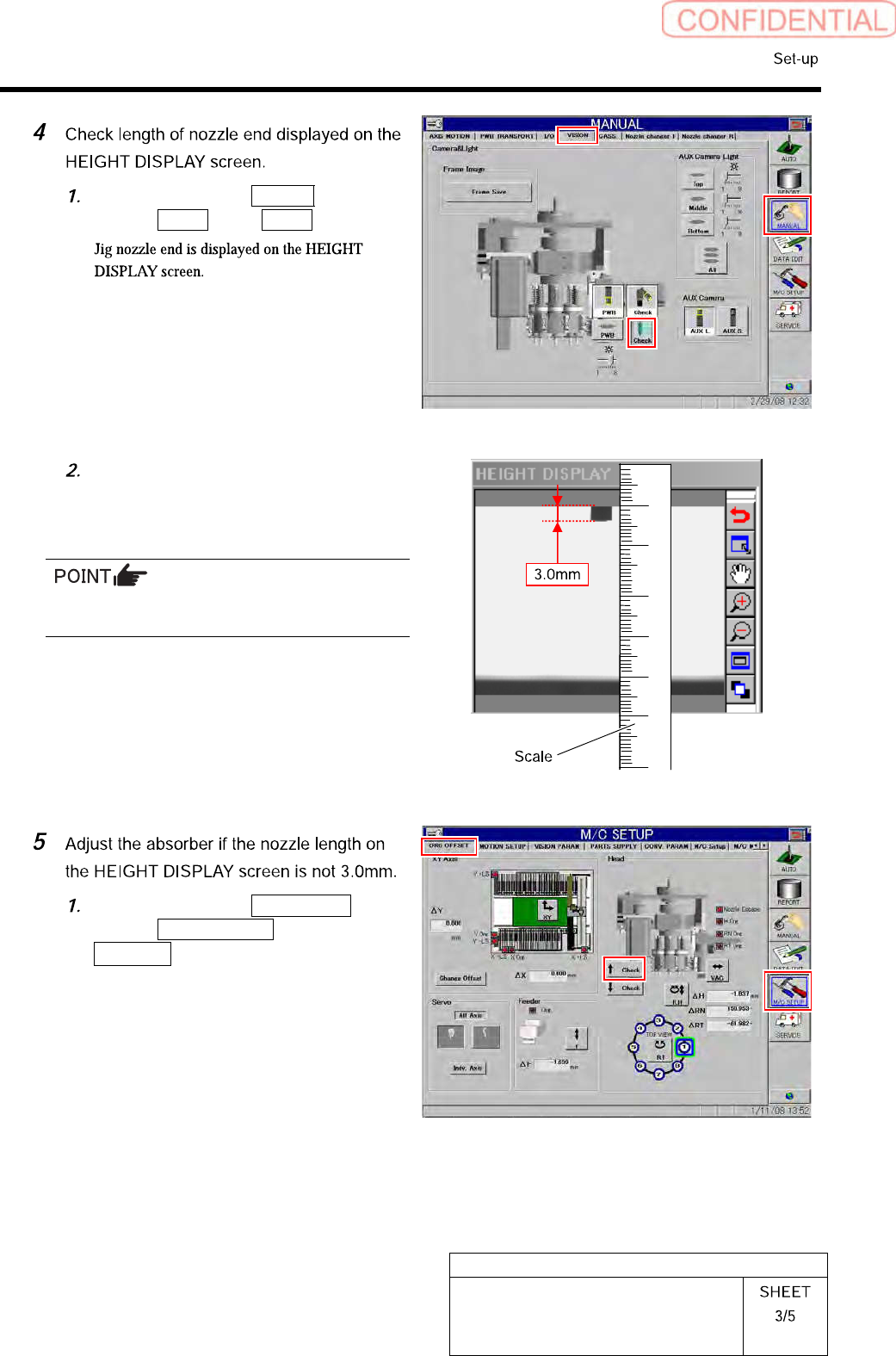
Click in an order of Manual
menuVision tab Check button.
Apply a scale on the screen to check
that length of the displayed jig nozzle
end is 3.0mm.
For actual dimension of the nozzle, end of 1mm
is displayed on the screen.
Click in an order of M/C SETUP
menuORG OFFSET tab
↑ Check button to raise the Pickup
check camera.