MAN00000772_SI-G200BB_SVCPDFA.pdf - 第323页
HLGB-10413-01 Nozzle Escape Detect Sensor Position Adjustment Set the “2. T imer function” to “------ (timer ineffective)” and p ress the MODE button. Set the “3. MODE key se tting” to “(Power tuning ex ecution)” and pre…
HLGB-10413-01
Nozzle Escape Detect Sensor
Position Adjustment
Tighten the split fastening screw.
Rotate the nozzle by one turn, and
check that laser from light emitting
section is emitted to the reflector plane
at every angle.
Check that there’s some clearance
between the end of the nozzle omission
detection sensor and the nozzle O-ring
spring.
Check clearance at the ceramic ball section.
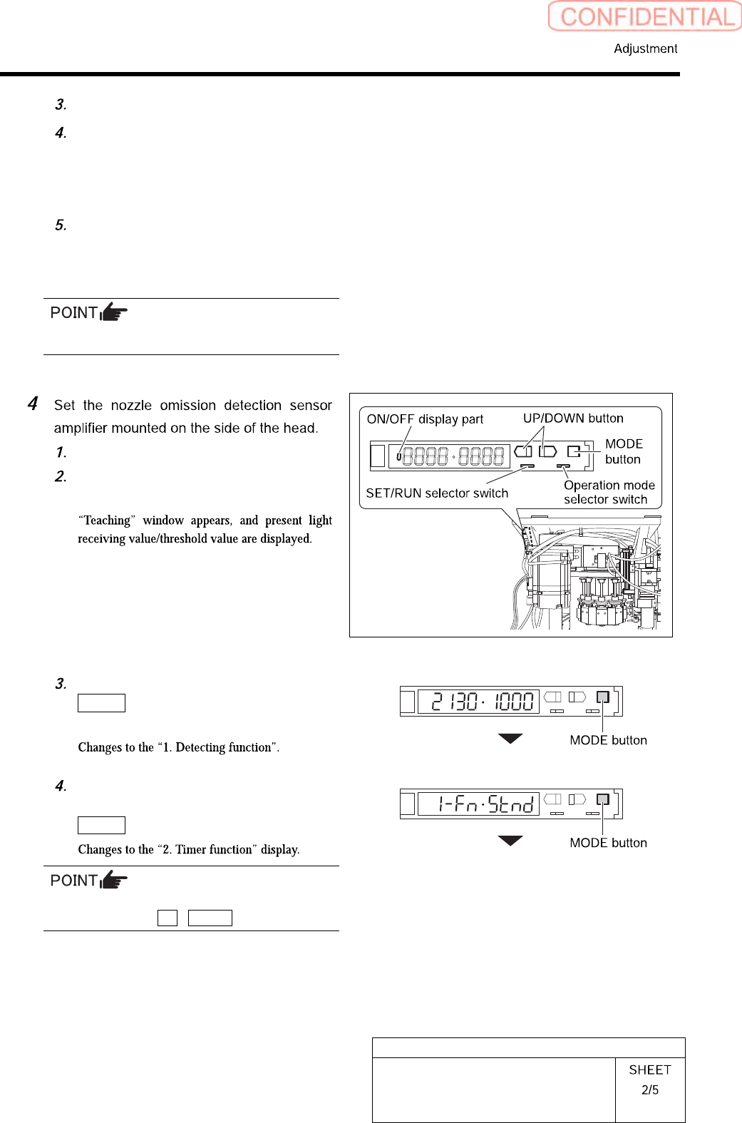
Open the cover of the sensor amplifier.
Turn the SET/RUN selector switch to
the “SET” side.
On “Teaching” display, press the
MODE button to change the display
without doing anything.
Set the “1. Detecting function” to the
“Std (standard setting)” and press the
MODE button.
To change the selecting items on each set
display, press the UP / DOWN button.
HLGB-10413-01
Nozzle Escape Detect Sensor
Position Adjustment
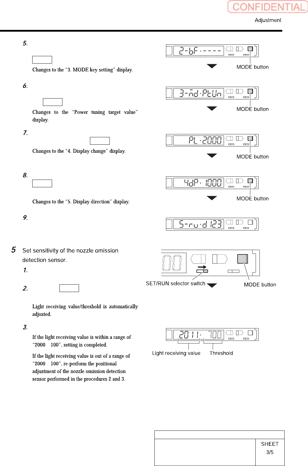
Set the “2. Timer function” to “------
(timer ineffective)” and press the
MODE button.
Set the “3. MODE key setting” to
“(Power tuning execution)” and press
the MODE button.
Set the “Power tuning target value” to
“2000” and press the MODE button.
On the “4. Display change”, press the
MODE button without doing
anything.
Set the “5. Display direction” to “D123
(normal setting)”.
Turn the SET/RUN selector switch to
the “RUN” side.
Press the MODE button for longer
than 3 seconds.
L
SET RUN
UP DOWN MODE
D
Check the light receiving value.
±
±
HLGB-10413-01
Nozzle Escape Detect Sensor
Position Adjustment
L
SET RUN
UP DOWN MODE
D
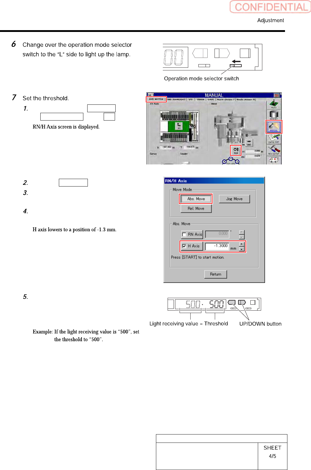
Click in an order of MANUAL menu
AXIS MOTION tab R.H button.
Click the Abs. Move button.
Click the check box for H axis and put
check in it to input “-1.3”.
Press the [START] button on the
operation panel.
Check the present light receiving
value with the nozzle omission
detection sensor amplifier, and set its
value to the threshold.