MAN00000772_SI-G200BB_SVCPDFA.pdf - 第246页
HLGB-1031 1- 01 Pickup Position Setup Click in an o rder of M/C SETUP menu P ART S SUPPL Y tab. Click the T eaching button on the Fro nt Pos. Data to disp l ay a drop d own menu. Click the Jigs in the drop down menu. C…
HLGB-10311-01
Pickup Position Setup
Pickup position setup can be performed at three locations on the front cassette table (Z106, Z120,
Z139) and at three locations on the rear cassette table (Z106, Z120, Z135).
Perform pickup position setup for tray specification only on the rear side cassette table (Z101, Z108,
Z117).
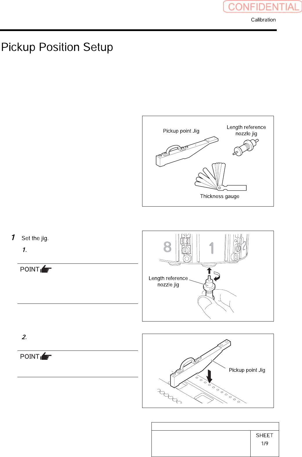
[Necessary jigs]
• Pickup point Jig
• Length reference nozzle jig
• Thickness gauge
[Preparation before work]
Install the length reference nozzle jig
to the turret No.1.
When installing the nozzle, insert it while
slowly turning.
After inserting the nozzle, check that it is not
drawn out by pulling downward.
Set pickup point jig to Z106 on the
cassette table.
There should be no gap between the feed
adjusting jig and the cassette table.
HLGB-10311-01
Pickup Position Setup
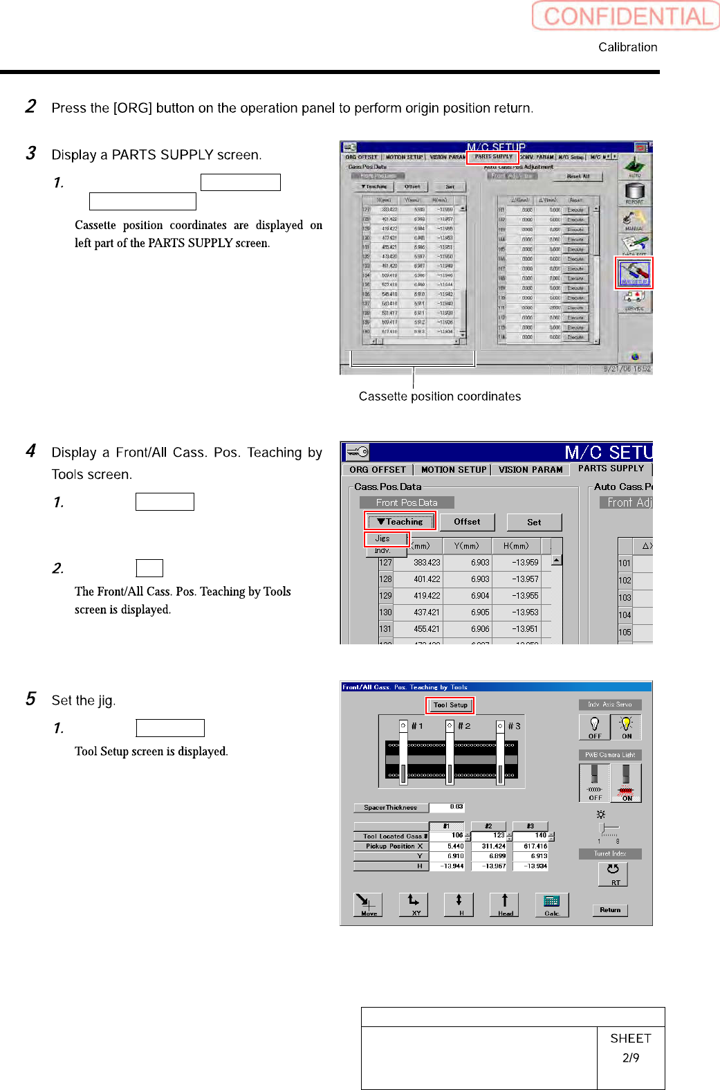
Click in an order of M/C SETUP menu
PARTS SUPPLY tab.
Click the Teaching button on the Front
Pos. Data to display a drop down
menu.
Click the Jigs in the drop down menu.
Click the Tool Setup button.
HLGB-10311-01
Pickup Position Setup
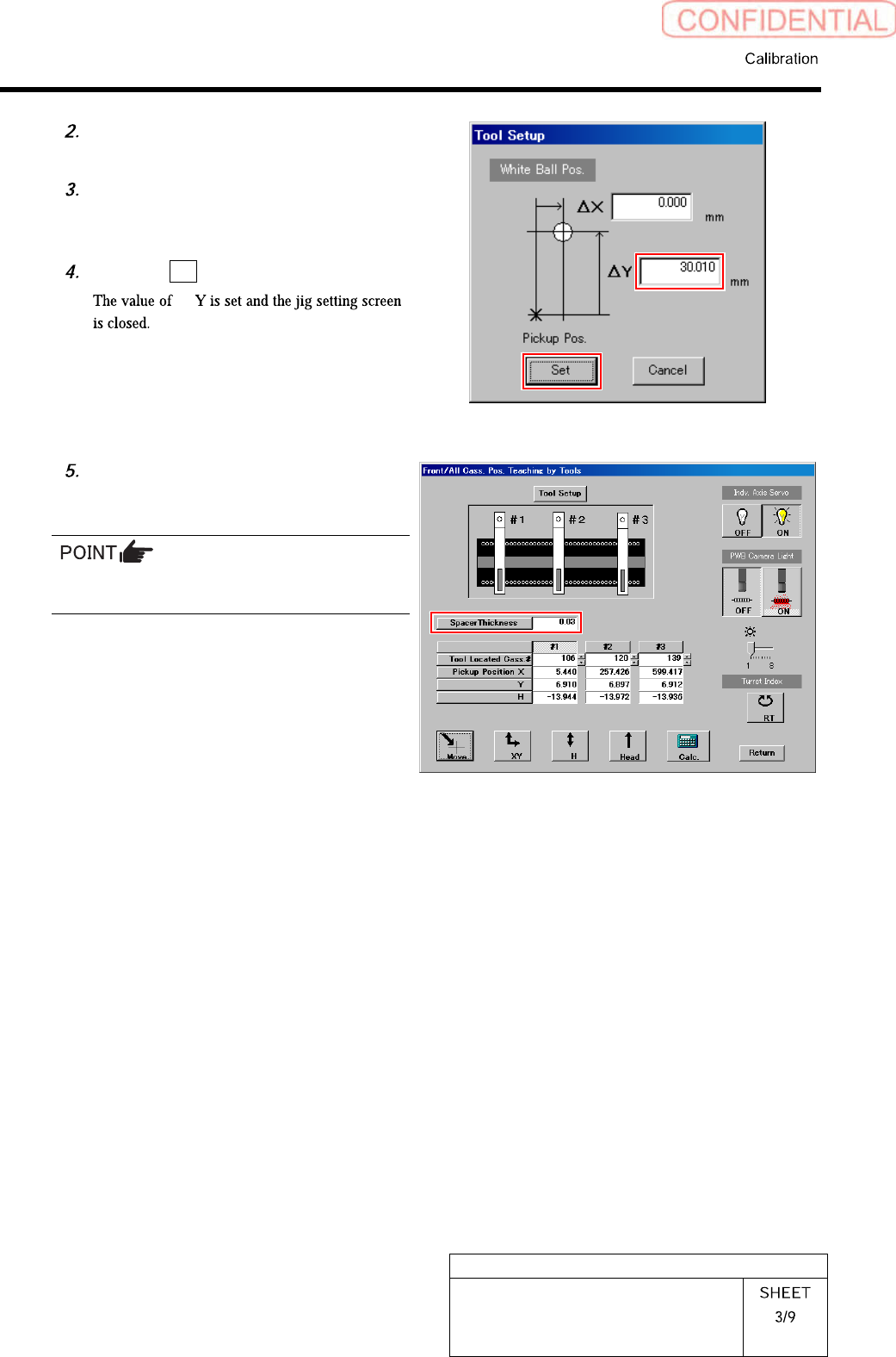
Check jig information (ΔY) attached
on the side of the pickup point jig.
Enter value ofΔY written on the side
of the pickup point jig into the ΔY box
on the jig setting screen.
Click the Set button.
Δ
Input thickness of “0.03” of thickness
gauge used for H axis position data
teaching.
The value of the spacer thickness becomes
offset value when acquiring H coordinate.