MAN00000772_SI-G200BB_SVCPDFA.pdf - 第324页
HLGB-10413-01 Nozzle Escape Detect Sensor Position Adjustment L SET RUN UP DOWN MODE D Click in an order of MANUAL menu AXIS MO TION tab R.H button. Click the Abs. Move button. Click the check box for H axi s an d pu…
HLGB-10413-01
Nozzle Escape Detect Sensor
Position Adjustment
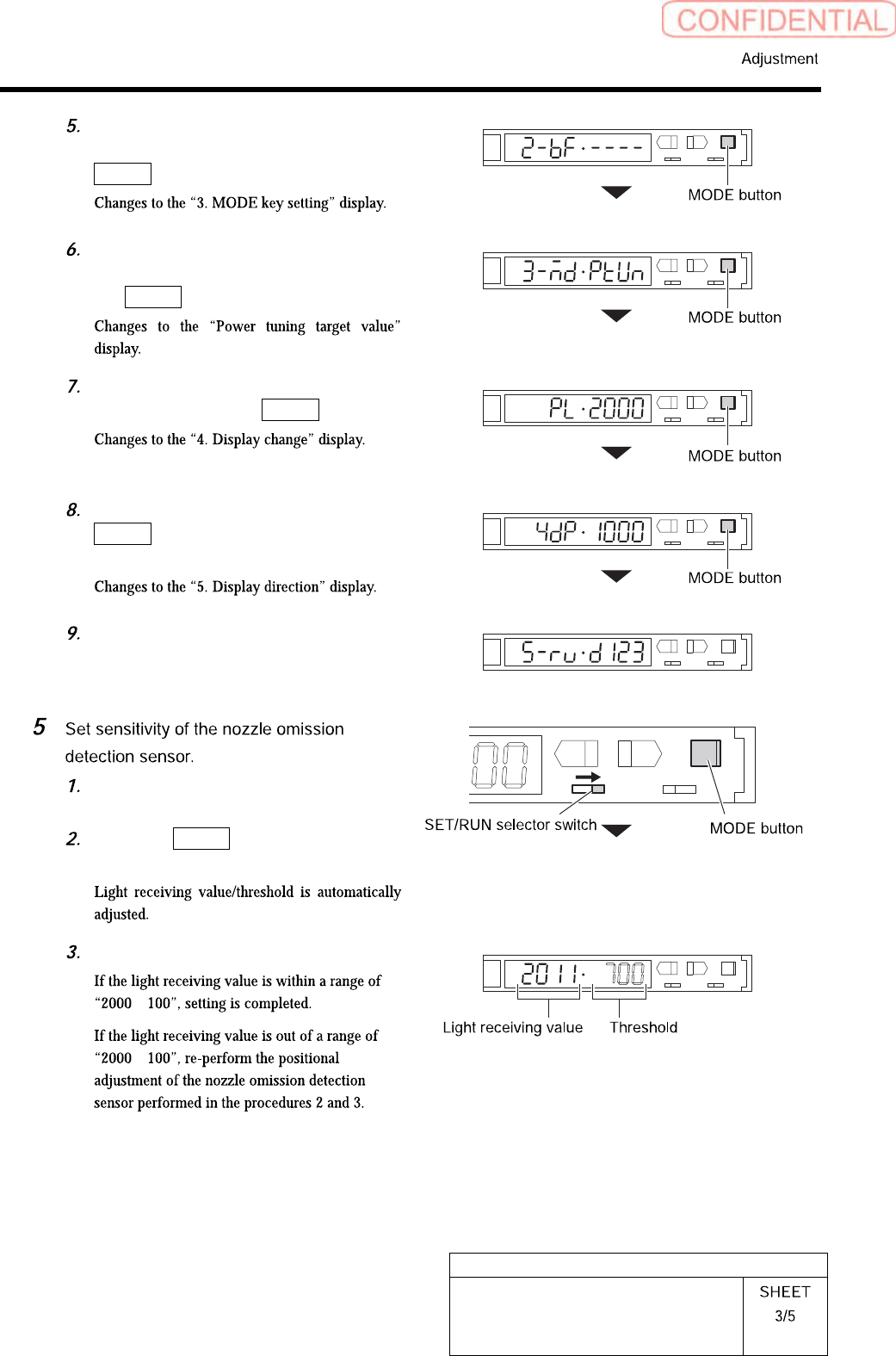
Set the “2. Timer function” to “------
(timer ineffective)” and press the
MODE button.
Set the “3. MODE key setting” to
“(Power tuning execution)” and press
the MODE button.
Set the “Power tuning target value” to
“2000” and press the MODE button.
On the “4. Display change”, press the
MODE button without doing
anything.
Set the “5. Display direction” to “D123
(normal setting)”.
Turn the SET/RUN selector switch to
the “RUN” side.
Press the MODE button for longer
than 3 seconds.
L
SET RUN
UP DOWN MODE
D
Check the light receiving value.
±
±
HLGB-10413-01
Nozzle Escape Detect Sensor
Position Adjustment
L
SET RUN
UP DOWN MODE
D
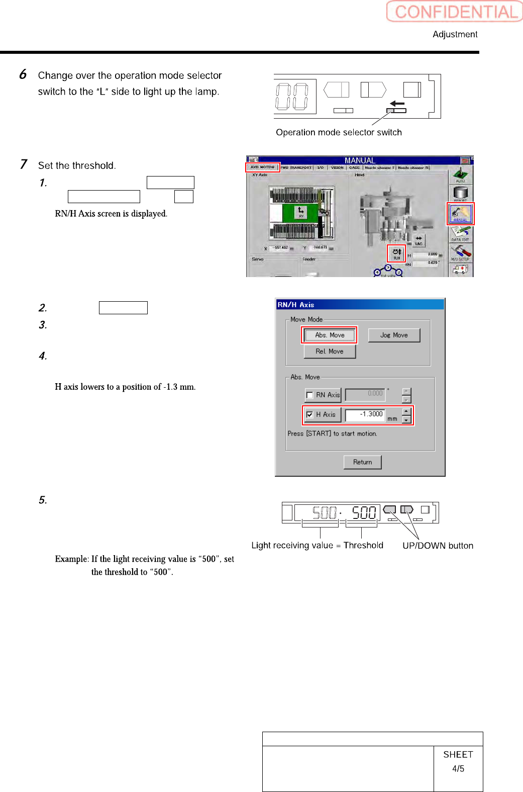
Click in an order of MANUAL menu
AXIS MOTION tab R.H button.
Click the Abs. Move button.
Click the check box for H axis and put
check in it to input “-1.3”.
Press the [START] button on the
operation panel.
Check the present light receiving
value with the nozzle omission
detection sensor amplifier, and set its
value to the threshold.
HLGB-10413-01
Nozzle Escape Detect Sensor
Position Adjustment
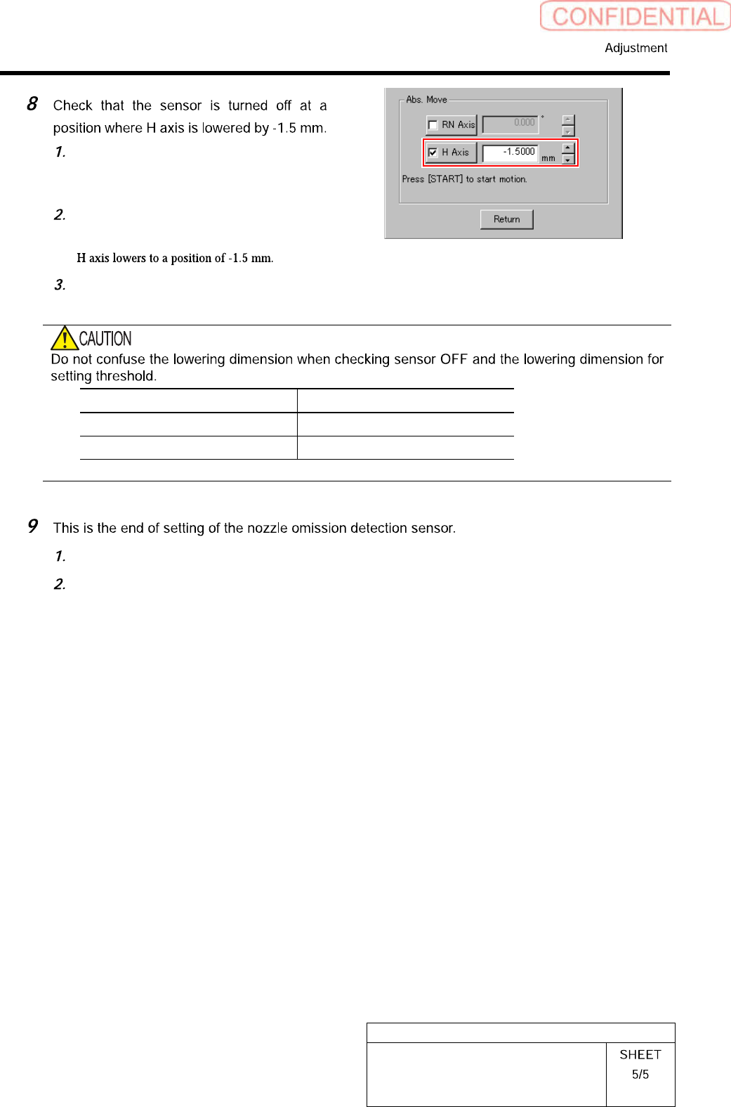
On the RN/H Axis screen, click check
box for H axis and put check in it to
input “-1.5”.
Press the [START] button on the
operation panel.
Check that the sensor is turned off.
Item H Axis lowering dimension
Threshold setting -1.3 mm
Sensor OFF check -1.5 mm
Close the cover for the nozzle omission detection sensor amplifier.
Remove the nozzle for production installed on the head.