MAN00000772_SI-G200BB_SVCPDFA.pdf - 第259页
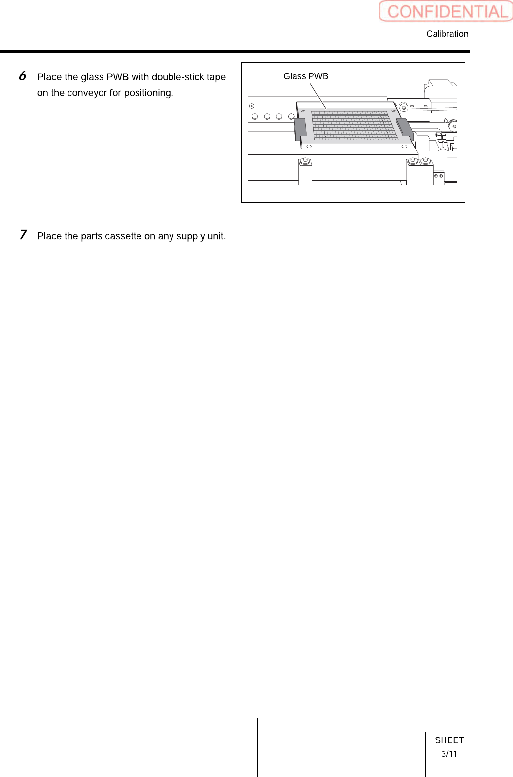
HLGB-10313-01 Mount A ccuracy Calibration Click in an ord er of PWB TR ANSPORT tab Conv . W id. Adj. button. Click the Abs. Move button. Input “70” into the input box of the Conv . Width Abs. Pos. Press the [ST ART ] b…
HLGB-10313-01
Mount Accuracy Calibration
By recognizing the mounted part position with the PWB camera, this system can calculate the
correction value and calibrate the mount position. When the pickup position is unstable, the stability
of the mounting accuracy may not be assured. Before applying the calculated correction value,
execute the test mounting two or three cycles.
There are two calibration modes: “Transcription calibration” and “Batch recognition calibration”. Be
sure to execute the batch recognition calibration after executing the transcription calibration.
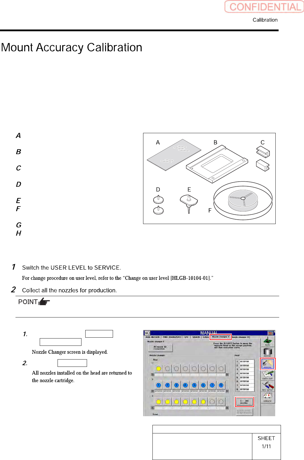
[Necessary jigs]
Glass PWB for easy measurement
(Accuracy improvement function kit)
Glass PWB frame for easy measurement
(Accuracy improvement function kit)
Clamp (Accuracy improvement function
kit)
Knurled knob with pad (Accuracy
improvement function kit)
BF1305R nozzle (8 pcs.)
Mounting accuracy correction jig 1005C
chip (3-276-548-01)
Parts cassette GAK0802/P100
Double-stick tape
[Preparation before work]
When BF1305R nozzles are attached to all the Indexes, this step is not required.
Click in an order of MANUAL menu
Nozzle changer tab.
Click the All nozzles button.
HLGB-10313-01
Mount Accuracy Calibration
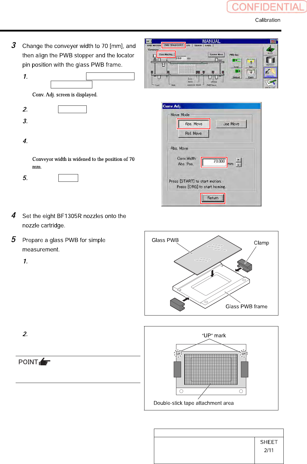
Click in an order of
PWB TRANSPORT
tab Conv. Wid. Adj. button.
Click the Abs. Move button.
Input “70” into the input box of the
Conv. Width Abs. Pos.
Press the [START] button on the
operation panel.
Click the Return button to close the
Conv. Adj. screen.
Put glass PWB on glass PWB frame
and hold it with clamp.
Attach double-stick tape on area of the
glass PWB in the figure.
Attach the double-stick tape paying attention to
the position and tape attachment area.
HLGB-10313-01
Mount Accuracy Calibration