MAN00000772_SI-G200BB_SVCPDFA.pdf - 第191页
HLGB-10206-01 F A xis Setup Click in an order of MANUAL menu CASS. tab. Input “120” into the cas sette po sition space, and click the Move . Press the [ST ART] butto n on the operation panel. Replace the parts feed hei…
HLGB-10206-01
F Axis Setup
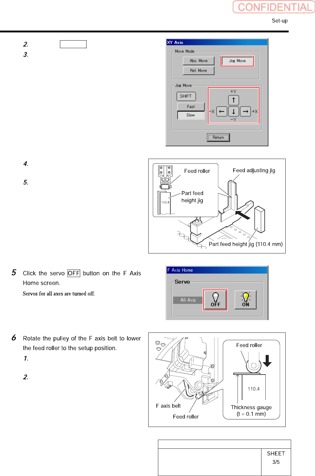
Click the Jog Move button.
Press the cursor key to move the feed
part onto the feed adjusting jig.
Place the part feed height jig
(110.4mm) on the feed adjusting jig.
Adjust position so that center of the
feed roller is on the center of the part
feed height jig.
Pinch a thickness gauge of 0.1mm on
the part feed height jig.
Rotate the pulley of the F axis belt to
lower the feed roller to a position
where it contacts the thickness gauge.
HLGB-10206-01
F Axis Setup
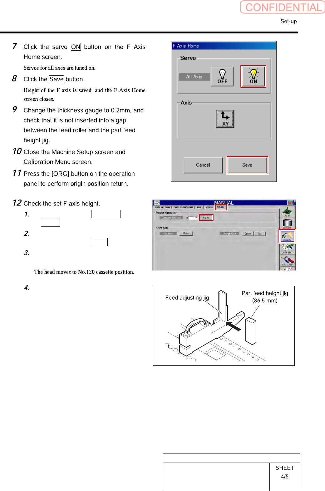
Click in an order of MANUAL menu
CASS. tab.
Input “120” into the cassette position
space, and click the Move.
Press the [START] button on the
operation panel.
Replace the parts feed height jig
(110.4mm) on the feed adjustment jig
with a parts feed height jig of 86.5mm.
HLGB-10206-01
F Axis Setup
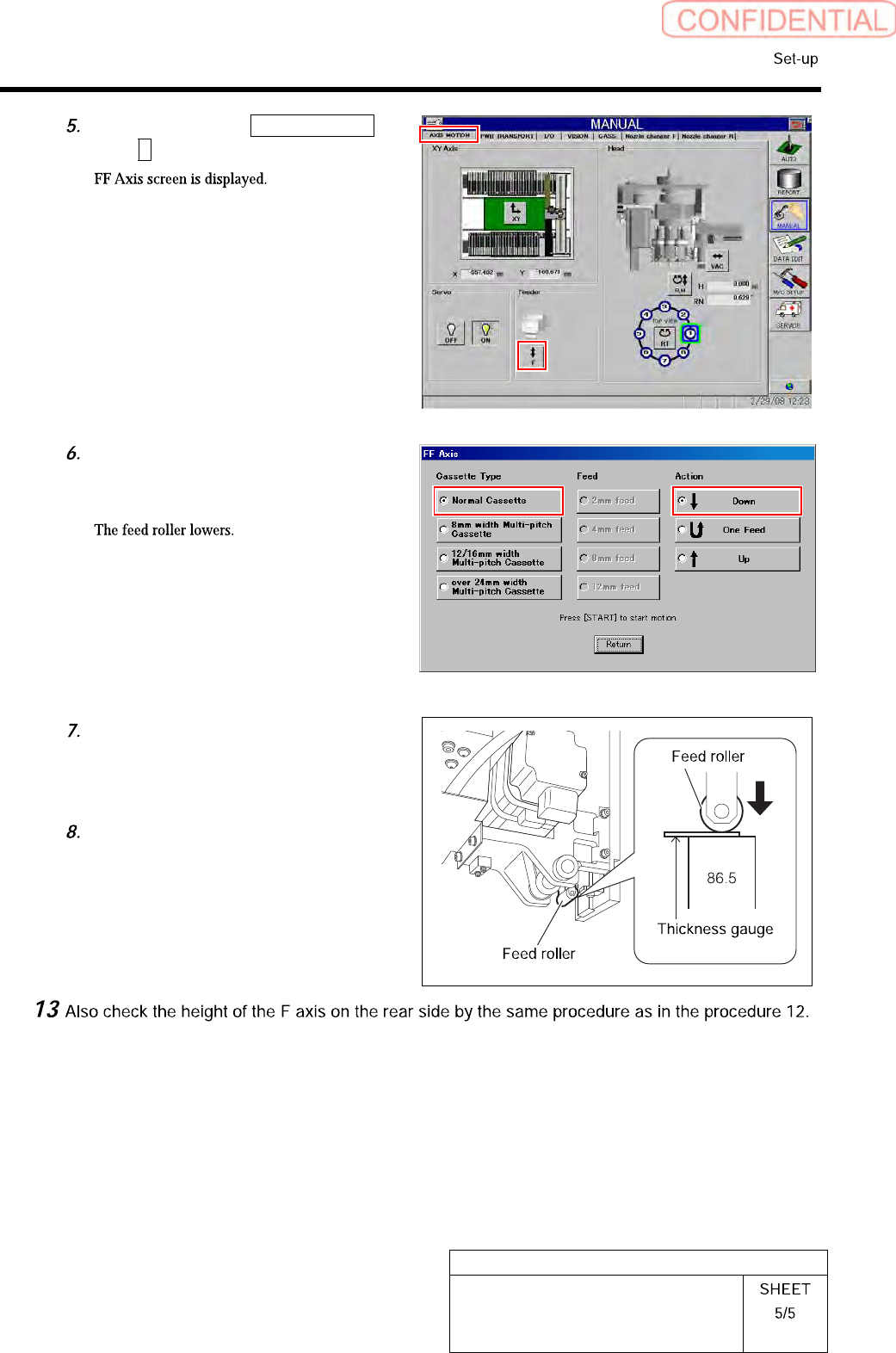
Click in an order of AXIS MOTION
tabF button.
Place a check in “Normal Cassette”
and “Down” and press the [START]
button on the operation panel.
Check that clearance between the
parts feed height jig (86.5mm) and the
feed roller is in a range of 0<0.2mm
with a thickness gauge.
After checking, place a check in the
“Up” on the FF axis careen, and press
the [START] button.