IPC-7095C-2013.pdf - 第101页
created more fragile package constructions, particularly in the areas of shock and bend. Electronic devices are getting smaller and smaller . Smaller devices tend to be carried more and dropped more which leads to more d…
7.2 Post-SMT Processes
7.2.1 Conformal Coatings
Conformal coatings are used
to protect the parts from surface moisture and thus corro-
sion. Conformal coatings should be specified to meet the
requirements of IPC-CC-830 and should be specified on
the master assembly drawing. When UL requirements are
imposed, the coatings shall be approved by UL for use by
the printed board manufacturer.
The designer should be cognizant of compatibility issues.
Conformal coating is an electrical insulation material
which conforms to the shape of the circuit board and its
components. It is applied for the purpose of improving sur-
face dielectric properties and protecting them from the
effects of a severe environment. Conformal coatings are
not required on surfaces or in areas that have no electrical
conductors (see IPC-2221, Section 4.5.2).
Conformal coatings may be any of five types. The thick-
ness of the conformal coatings shall be as follows for the
type specified:
• AR - acrylic resin, 0.03 to 0.13 mm
• ER - epoxy resin, 0.03 to 0.13 mm
• UR - urethane resin, 0.03 to 0.13 mm
• SR - silicone resin, 0.05 to 0.21 mm
• XY - paraxylene resin, 0.01 to 0.05 mm
There are three primary chemical categories in use for con-
formal coatings. These are: silicone elastometers, parylene,
and other organics. All conformal coating types provide
various levels of protection from solvents, moisture, corro-
sion, arcing and other environmental factors that can jeop-
ardize the circuit operation.
Conformal coatings may also be used in greater thicknesses
as shock and vibration dampening agents. This type of
application brings with it the risk of mechanical stress to
glass and ceramic-sealed parts during cold temperature
excursions. Using this material may require the use of buf-
fer materials.
Caution should be taken to prevent underfilling BGAs with
conformal coating materials. Testing has shown that when
completely underfilling BGAs with conformal coating
materials (other than paraxylene) solder joint fatigue fail-
ures resulted during thermal cycle testing due to ‘‘Z’’ axis
expansion. Thus, the use of conformal coating as an under-
fill is not recommended.
Conformal coating should not be confused with encapsu-
lants. Encapsulants are used primarily to protect the bare
die as a part of the chip component package. Plastic encap-
sulants provide the protection of the plastic BGA from
external sources. The compatibility issues of encapsulants
and thermal coatings are very similar.
7.2.2 Use of Underfills and Adhesives BGAs may
require the use of adhesives to further strengthen the pack-
age to PCB interconnection. In recent years the implemen-
tation of lead-free solders and the reduction in pitches has
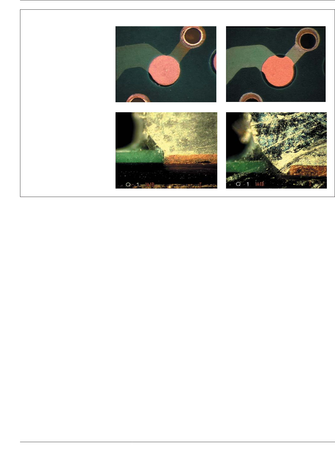
IPC-7095c-7-10a,b,c,d
Figure 7-10 Effect of Having Solder Mask Relief Around the BGA Lands of the Board
Solder Mask Relief Around Land ~0 mm 0.75 mm
Top view of land illustrating
increase of effective land diameter
due to trace connections
Cross-sectional view of land with
solder ball joint illustrating the sol-
der wetting down the edge of the
land when there is solder mask
relief away from the land edge
IPC-7095C January 2013
86
Copyright IPC-Association Connecting Electronics Industries
Provided by IHS under license with IPC
Not for Resale
No reproduction or networking permitted without license from IHS
--`,,```,,,,````-`-`,,`,,`,`,,`---

created more fragile package constructions, particularly in
the areas of shock and bend. Electronic devices are getting
smaller and smaller. Smaller devices tend to be carried
more and dropped more which leads to more demanding
shock and drop specifications. These factors are driving
underfills and structural adhesives to be commonplace in
electronics packaging.
Polymeric reinforcement of BGA packages is rapidly mov-
ing into many electronics applications. Early adopters of
these methods include the markets such as cell phones,
MP3 players, PDAs, cameras, medical electronics, avionics
and military applications. More recent markets that are
using underfills and other epoxies include laptop mother-
boards and ultra mobile PCs. Desktop motherboards and
server boards have resisted implementation of polymeric
BGA reinforcement. However, as BGA packages get more
fragile, this approach is also a possibility in these markets.
Three polymeric approaches for strengthening the BGA to
PCB interconnection are popular in the marketplace. These
include full capillary flow underfill, partial capillary flow
underfill, and corner applied adhesive. No flow underfill
technologies are being developed, but High Volume Manu-
facturing (HVM) adoption of this approach has not yet
occurred. Some studies have shown that roughly a 100 to
200% improvement in package performance can be seen in
representative packages in shock and bend performance
versus packages with no polymeric reinforcement. Poly-
meric reinforcement of BGA is better than many other
approaches that have been tried. (larger land sizes, metal
defined lands, alternate land shapes, etc.).
The form factor, i.e., body size of and/or ball pitch, of
BGA Packages is not the main determinant factor for their
polymeric reinforcement. The market segment in which the
BGA components are used is more critical in determining
whether corner glue or underfill is required or not. The
owner of the product design must determine if the product
needs additional mechanical protection for BGA packages
to meet marketplace specific reliability requirements (e.g.,
shock, bend, vibration, drop, temperature cycling, etc.)
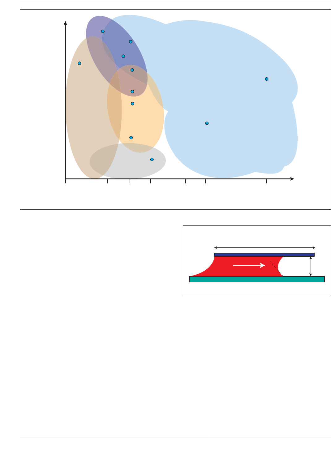
Figure 7-11 shows a conceptual map of some typical types
of adhesive approaches overlaid into reliability require-
ments versus designed product life for a sampling of elec-
tronics devices. In this map, three distinct adhesive
approaches are conceptually grouped.
The first grouping is assembled with the high performance
underfills. These include devices that have the highest
class of expected performance in both temp cycle and
shock. Devices in this class can have expected product life
expectancies of 10-20 years or more and include avionics,
military electronics, medical devices and automotive elec-
tronics. The underfills used typically have low molecular
weight resins and are highly filled with smaller particle size
fillers to minimize any void formation and filler segrega-
tion during flow. These materials may require longer dura-
tion cure cycles and are not reworkable. In this market,
performance is the ultimate driver, not cost.
The next grouping is categorized as process oriented
underfills. These products include things like cell phones
and smart phones, MP3 players, and tablet PCs. In this
market, high performance in shock is required. Tempera-
ture cycle performance is not as demanding probably
because these mobile devices run cooler with less power
consumption. In this consumer market, cost is very impor-
tant. The resulting underfills used are made from resins
which flow quickly and cure more quickly at lower tem-
perature. The resulting underfills can sometimes even be
reworked. These attributes maintain high beat rates and
minimize scrap to keep total costs down.
The final grouping of products uses corner glue adhesives.
(Corner glue is similar in concept to corner bond or edge
bond names used by particular manufacturers.) Devices
that use this strategy include laptop PCs, tablet PCs, net-
books, sometimes desktop PCs, and rarely servers. These
devices tend to be less portable that the prior group and, as
a result, their shock requirements are less demanding. The
corner glue strategy provides less shock performance than
the underfill strategies. Corner glue has the advantages
over underfill in that this approach is more easily
re-workable and less expensive to implement in terms of
capital, material cost and labor cost. Some corner glue
adhesives are even formulated to cure with a short expo-
sure to UV light. This can eliminate the need for more
expensive cure ovens and replace them with a bank of UV
lights.
As would be expected, high performance with these poly-
meric reinforcement strategies can only be obtained by
choosing the right material for the specific application
using experimentation. Underfill users should be aware that
choosing an underfill chemistry with cured mechanical
properties that match the use environment is critical.
Underfill chemistries generally increase mechanical perfor-
mance of packages (shock, bend, vibration, and drop) but
if they are not selected properly they can degrade the tem-
perature cycling performance at the same time. Hence,
margin gain in mechanical shock reliability needs to be
balanced with risk of margin loss in the temperature cycle
reliability.
7.2.2.1 Full Underfill and Partial Underfill Full underfill
is usually done by applying uncured liquid polymer to the
board at the edge of the BGA package and allowing the
underfill to flow underneath the BGA package via capillary
action. Care must be taken when designing the underfill
dispense process to avoid the capture of a large air bubble
(void) in the interior of the BGA package. Dispense pat-
terns such as an ‘‘I’’ shaped dispense down one side of the
package are much less likely to entrap bubbles than the
January 2013 IPC-7095C
87
Copyright IPC-Association Connecting Electronics Industries
Provided by IHS under license with IPC
Not for Resale
No reproduction or networking permitted without license from IHS
--`,,```,,,,````-`-`,,`,,`,`,,`---
faster to flow ‘‘L’’ or ‘‘U’’ shaped patterns (down two sides
or three sides respectively).
Underfill can be dispensed around packages on boards
either with automated equipment (jet dispense or auger
pumps or others) or with manual equipment (pneumatic
dispense through a syringe and needle). To increase the
flow rate of the underfill and the production rate of the
manufacturing line, assembled boards are often preheated
to between 50°-110°C. Underfill vendors recognize that
flow rate drives production rate. More recent generations of
underfills are being formulated with lower viscosities and
better wetting characteristics that significantly increase
flow rates. Newer generation underfills that flow well with-
out preheating of PCBs are also being introduced.
Capillary underfill flow time when dispensed using an ‘‘I’’
pattern can be approximated with the following equa-
tion:(1) (see Figure 7-12).
T = (3µL
2
)/(hγ cos Θ) where,
T = for underfill to flow across the package in seconds
µ = underfill viscosity
L = distance for underfill to flow
h = gap between parallel surfaces
Θ = wetting angle of fluid to surfaces
γ = surface tension of underfill
Voids in underfill are common, especially at the intersec-
tion of the solder ball and the PCB and the solder ball and
the package substrate. General consensus is that small
voids in the bulk underfill have no significant effect on
performance in shock, bend, or temperature cycling. There
is no industry standard for allowable voids in underfill.
However, most underfill users recognize that any voids in
the underfill that connect adjacent solder are risky. (Solder
has been shown to creep through voids and short adjacent
solder balls in temperature cycling.) Moderate sized voids
(i.e., getting larger than half of the diameter of a solder
ball) are a grey area in terms of industry acceptance. Anec-
dotal evidence says that these moderate sized voids do not
have significant adverse effects but some underfill users
would like to eliminate them from occurring in their pro-
cess. Figure 7-13 shows examples of small halo voids,
medium sized voids and large voids, respectively.
IPC-7095c-7-11
Figure 7-11 Map of Underfill Adhesive Usage for BGA and Other Packages
0
Increasing Reliability Requirements
Designed Product Life in years
low end phones
smart phones
3 7 10 12 205
Solid state drives
MP3 players
tablet PCs
net book PCs
laptop PCs
desktop PCs
servers
automotive
computing
avionics
military–
missile
guidance
other high end
electronics
medical
electronics
HIGH
PERFORMANCE
UNDERFILLS
PROCESS
ORIENTED
UNDERFILLS
CORNER
GLUES
NO ADHESIVES
IPC-7095c-7-12
Figure 7-12 Flow of Underfill Between Two Parallel Sur-
faces
γ
µ,
θ
h
L
IPC-7095C January 2013
88
Copyright IPC-Association Connecting Electronics Industries
Provided by IHS under license with IPC
Not for Resale
No reproduction or networking permitted without license from IHS
--`,,```,,,,````-`-`,,`,,`,`,,`---