IPC-7095C-2013.pdf - 第134页
For eutectic tin/lead BGA solder joints, during temperature cycling, grain coarsening occurs in areas of the solder joint where the strains due to thermal mismatch build up. These coarser grains are softer than the origi…

8.1.5 Mechanical reliability Mechanical reliability refers
to the response of the BGA interconnect to a mechanical
stimulus. These stimuli include shock events, which may
occur during shipping, installation, or field use, transient
bend, which may occur during manufacturing (in-circuit
test, functional test, installation, etc.) or in the field, cyclic
bend, such as repetitive keystrokes near a BGA, or vibra-
tion due to fans, or motors near or in the system. All of
these stimuli, and others, can have an effect on the
mechanical integrity of the BGA interconnect, and all of
them should be considered when using BGAs, which are
particularly susceptible to flexure based stressors.
8.1.5.1 Shock A shock event is characterized by signifi-
cantly high-speed, which does not allow time for intercon-
nect materials to respond to the applied force. Shock can be
induced via drop or impact, and can occur at any time dur-
ing the life of the product, although shipping and end-user
environment shock events are most typical. Shock events
can result in a separation, either partial or full, of a BGA
interconnect, at any of the interfaces making up the full
interconnect attachment. Even a partial interfacial fracture
can eventually, over the life of a product, cause an electri-
cal failure in a BGA. More brittle materials and interfaces
are particularly susceptible to shock induced failures.
8.1.5.2 Transient Bend Transient bend, or flexure, is
characterized by a low number (typically 1-10 flexure
events) of relatively slow strain. These events can be
induced during manufacturing, especially in test fixtures
such as ICT or functional testers that use pogo-pin style
probes, during connector insertion, or screw-down of the
PCA into a chassis. Transient bend can also be induced
during unit repair, shipping, and in the end-user environ-
ment. As with shock, these failures typically occur at an
interconnect interface and can result in either a complete
open, or a latent field risk as partial fractures can eventu-
ally open in the field.
8.1.5.3 Cyclic Bend Cyclic bend is typified by multiple
relatively low-level strain events. These events can run into
the thousands or above, and are usually caused by repeti-
tive actions such as keypad actuation, transportation, and
connector insertion or extraction (such as in notebook
docking stations). Over time, fatigue failures may result.
8.1.5.4 Vibration Vibration is characterized by a con-
tinuous low-amplitude displacement of relatively high fre-
quency (as compared to the other mechanical stresses
described above). Vibration can impinge on a BGA due to
proximity of the component to a vibrating subsystem, such
as a motor, fan, or disk drive. It is possible, if the intercon-
nect system has already been stressed to the point of inter-
facial fracture, that vibration may exacerbate the issue,
leading to an electrical open; however, this is not yet well
understood.
8.2 Damage Mechanisms and Failure of Solder Attach-
ments
The reliability of an electronic assembly depends
on the reliability of the sum of the individual elements of
the mechanical thermal and electrical interfaces (or attach-
ments) between these elements. One interface type, the sur-
face mount solder attachment, is unique since the solder
joint not only provides the electrical interconnection, but is
also the sole mechanical attachment of the electronic com-
ponents to the printed board. It often provides the critical
heat transfer function as well. A solder joint in isolation is
neither reliable nor unreliable; it becomes so only in the
context of application.
The characteristics of these three elements—component,
substrate, and solder joint—together with the use condi-
tions, the design life, and the acceptable failure probability
determine the reliability of the surface mount solder attach-
ment.
The general characteristics of most lead-free solders as
compared to tin/lead solders, include (1) significantly
increased alloy stiffness, (2) significantly slower creep
rates, (3) greater difficulties of proper spread, and (4) sig-
nificantly higher soldering temperatures.
The consequence of the greater stiffness or lower ductility
and the slower creep rates are higher stresses on the whole
solder attachment structure during either temperature
changes, causing thermal expansion mismatches or PCB/
component warping, or bending. These higher stresses,
combined with less strong solder to base material connec-
tions due to inadequate wetting or interfacial structural
weaknesses, may cause brittle interfacial failure.
8.2.1 Comparison of Thermal Fatigue Crack Growth
Mechanism in SAC vs. Tin/Lead BGA Solder Joints
Eutectic tin/lead solder joints develop different damage
mechanisms than SAC BGA solder joints during Thermal
Fatigue Tests, such as Temperature Cycling. Eutectic tin/
lead solder microstructure is multi-grained, with each BGA
solder joints having many individual grains of lead-rich
(dark phase) and tin-rich (light colored phases) precipitated
out, as seen in Figure 8-1. In contrast, each SAC BGA sol-
der joint has very few grains of tin. These grains can be
seen under cross-polarizing light. Figure 8-2 shows two
examples of SAC BGA solder joints. The one on the left
has 6 grains, whereas the entire solder joint on the right is
comprised of a single grain.
January 2013 IPC-7095C
119
Copyright IPC-Association Connecting Electronics Industries
Provided by IHS under license with IPC
Not for Resale
No reproduction or networking permitted without license from IHS
--`,,```,,,,````-`-`,,`,,`,`,,`---
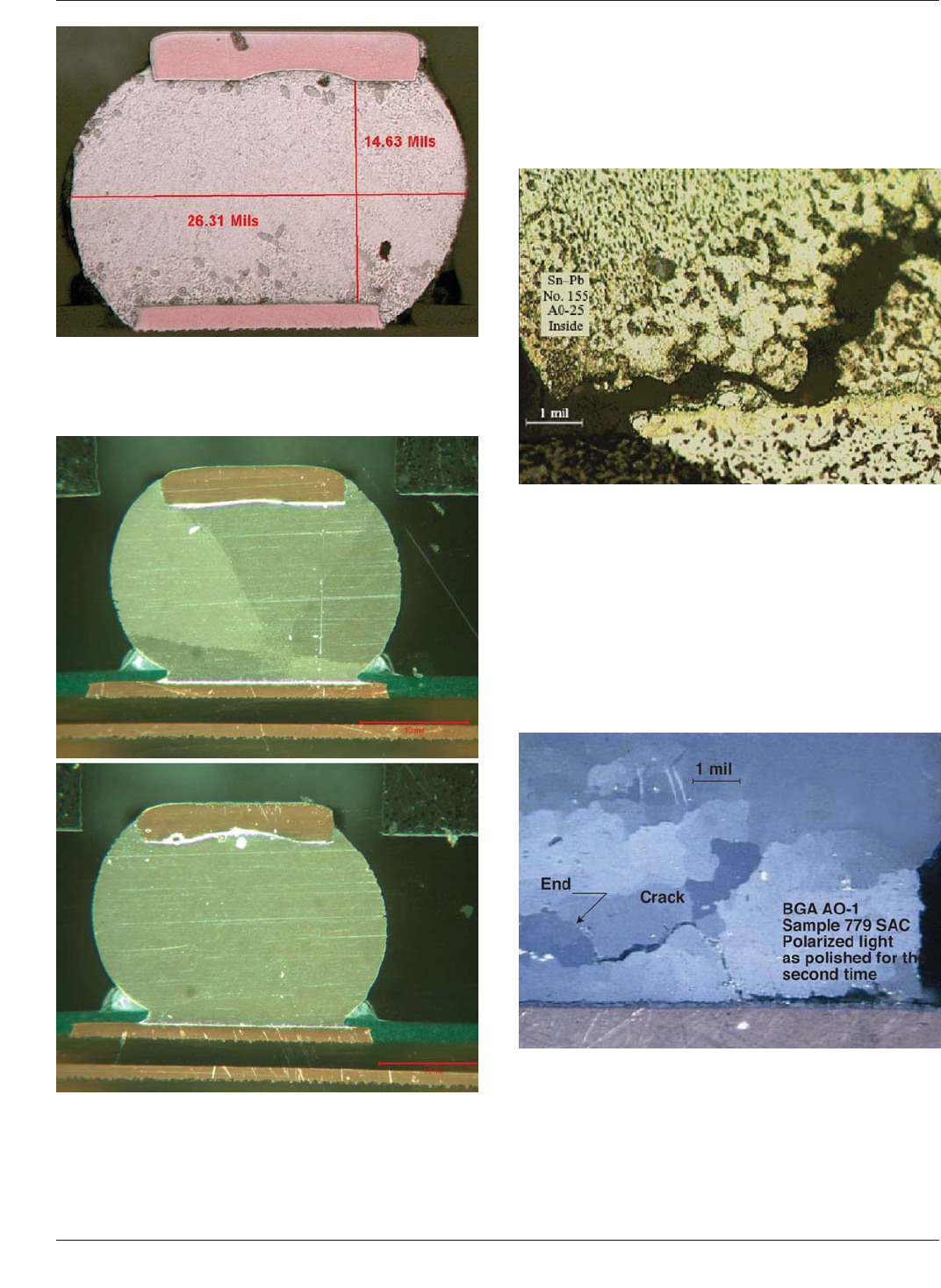
For eutectic tin/lead BGA solder joints, during temperature
cycling, grain coarsening occurs in areas of the solder joint
where the strains due to thermal mismatch build up. These
coarser grains are softer than the original as solidified
grains, and promote crack propagation. This is shown in
Figure 8-3.
For lead-free SAC BGA solder joints, when subjected to
thermal cycling, re-crystallization of grains takes place in
regions of large thermo-mechanical stress. These
re-crystallized grains are smaller in size than the original
grains and are more prone to grain boundary sliding and
hence creep deformation. This causes the fatigue cracks to
propagate through this re-crystallized region, as shown in
Figure 8-4.
Figure 8-1 BGA Solder Joint of Eutectic Tin/Lead Solder
Composition Exhibiting Lead Rich (Dark) Phase and Tin
Rich (Light) Phase Grains
Figure 8-2 Socket BGA Solder Joints of SnAgCu Compo-
sition, Showing the Solder Joint Comprised of 6 Grains
(Top Photo) and a Single Grain (Bottom Photo).
Figure 8-3 Thermal-Fatigue Crack Propagation in Eutectic
Tin/Lead Solder Joints in a CBGA Module
Figure 8-4 Thermal-Fatigue Crack Propagation in
Sn-3.8Ag-0.7Cu Joints in a CBGA Module
IPC-7095C January 2013
120
Copyright IPC-Association Connecting Electronics Industries
Provided by IHS under license with IPC
Not for Resale
No reproduction or networking permitted without license from IHS
--`,,```,,,,````-`-`,,`,,`,`,,`---

8.2.2 Mixed Alloy Soldering During the transition to
lead-free reflow soldering, there will be occasions when it
may be necessary to solder tin/lead and lead-free BGAs on
the same PCBA with tin/lead or lead-free solder. Soldering
mixed alloy BGAs is an undesirable scenario, but it is
likely to happen. The most likely scenario is soldering
lead-free BGAs with tin/lead solder. This scenario occurs
when a component supplier provides end-of-life (EOL) tin/
lead BGAs in favor of lead-free BGAs. When confronted
with this situation there are several options:
• Refuse to build the PCBA
• Reball the BGA with tin/lead solder balls (may not be
acceptable to all companies)
• Convince the supplier to provide a Sn/Pb version
8.2.2.1 Reflow Solder Using a Lead-Free Profile Some
companies have successfully soldered mixed alloy BGAs
and the reliability results have been acceptable in many
cases. Studies have shown that the homogeneous contami-
nation of SAC solder with <20% wt. Lead will not degrade
fatigue life below that of tin/lead. However, be very cau-
tious. Perform adequate reliability testing (cross-sections,
thermal cycling, shock testing) to confirm solder joint reli-
ability in the intended use environment.
All components on a mixed alloy (lead-free BGAs with
tin/lead solder) PCBA should be evaluated for lead-free
soldering process compatibility before soldering is
attempted. This evaluation will ensure that all components
will survive lead-free soldering temperatures. While most
tin/lead components are rated to a peak temperature of
230°C, evidence suggests that many tin/lead components
will survive lead-free soldering temperatures, though this is
not always the case. Once again, be very cautious.
Adequate reliability testing should be done to confirm reli-
ability expectations. Use Table 8-1 as a guide for compo-
nent compatibility with lead-free soldering process tem-
peratures.
8.2.2.2 Reflow Solder Using a Tin/Lead Profile When
the assembly comprises both lead-free SAC BGAs and tin/
lead BGAs and/or when the PCBA has not converted to a
lead-free system or is not required to be a lead-free system,
such as the RoHS exempted industry sectors/applications, a
tin/lead eutectic paste continues to be used.
Under such scenarios, a tin/lead eutectic reflow profile hav-
ing the adequate peak temperature, dwell time and proper
preheat must be used. More details about such scenarios
are contained in Section 7.
8.2.2.3 Implementation of BGAs with Low-Ag SAC, or
doped SAC, and Non-SAC BGA Ball Alloys
During the
initial lead-free transition, the BGA solder ball alloys used
typically matched the assembly process alloys of
Sn96.5Ag3.0Cu0.5 (SAC305), Sn95.5Ag3.8Cu0.7
(SAC387) or Sn95.5Ag4.0Cu0.5 (SAC405). Problems such
as balls dropping off and susceptibility to mechanical shock
and thermally-induced strains have led BGA suppliers to
evaluate and suggest the use of additional alloys for the
balls. For some packages, the change involves moving
from silver (Ag) content of 3-4% down to 1-3%. Depend-
ing on the specific Ag content, the reduced Ag content will
increase the melting point of the solder ball by as much as
10°C. This can have a significantly adverse impact on the
PCBA assembly process. Great care must to be taken when
introducing new alloys into BGAs and new alloyed BGAs
into the assembly process.
The addition of doping elements to SAC system have also
been studied, offering improvements in some aspects of
mechanical properties. However, these additions largely do
not change the physical properties, particularly do not
lower the melting temperature of the alloy. Some doping
elements may affect solder under-cooling, the formation of
Intermetallic, matrix properties, Other non-SAC alloys, by
taking an entirely different metallurgical approach, offer
lower melting temperature, thus substantially favorable
assembly process and better mechanical properties from
reliability point view. But these alloys are more costly in
raw materials.
8.2.2.4 PCA Manufacturing Impact of Pb-Free The new
lead-free BGA ball alloys may have an impact on the
printed circuit assembly (PCA) reflow process due to
Table 8-1 Tin/Lead Component Compatibility with Lead-Free Reflow Soldering
Tin/lead Component Type Compatibility
Ceramic resistors/capacitors Okay
Molded capacitors (tantalum) Use lead-free process temperature compatible components only
Aluminum electrolytic capacitors Use lead-free process temperature compatible components only
Molded ICs (SO, PLCC, QFP) Use lead-free process temperature compatible components only
Connectors, sockets, etc. Use lead-free process temperature compatible components only
Crystals, oscillators Use lead-free process temperature compatible components only
Transistors, diodes Okay
LEDs Use lead-free process temperature compatible components only
BGAs May or may not be Okay. Evaluate on a case-by-case basis
DIP switches Okay
January 2013 IPC-7095C
121
Copyright IPC-Association Connecting Electronics Industries
Provided by IHS under license with IPC
Not for Resale
No reproduction or networking permitted without license from IHS
--`,,```,,,,````-`-`,,`,,`,`,,`---