IPC-7095C-2013.pdf - 第129页
then liquid flux or the paste flux are commonly used when reattaching a BGA, especially BGAs with less than 208 balls. Flux is applied to the land pattern or the BGA solder spheres and the BGA is placed over it. One drawba…
is the maximum recommendations, so reballing a removed
BGA and reinstalling it would exceed this number. There-
fore, a reballed BGA will always exceed this limit. Many
OEMs do not allow re-balled BGAs, or re-use of any com-
ponent. One should check with the customer before pro-
ceeding.
If the component is to be reused and it is overmolded plas-
tic, it will have to be baked. These packages are nonher-
metic and therefore absorb water if they have been out of
a moisture controlled atmosphere longer than the time
allowed in J-STD-020. The baking process drives off mois-
ture and prevents the ‘‘popcorning effect,’’ which is water
vaporizing within the component during reflow and caus-
ing catastrophic failure. Another consideration before
removal concerns the components adjacent to the BGA. If
hot air is used, and if the profile to be used exceeds 4°C per
second, the components surrounding the BGA may need to
be shielded due to thermal shock or secondary reflow.
Polyimide tape or water soluble mask that is commonly
used in the wave solder processes can be used as shielding.
These deficiencies can be resolved with proper equipment
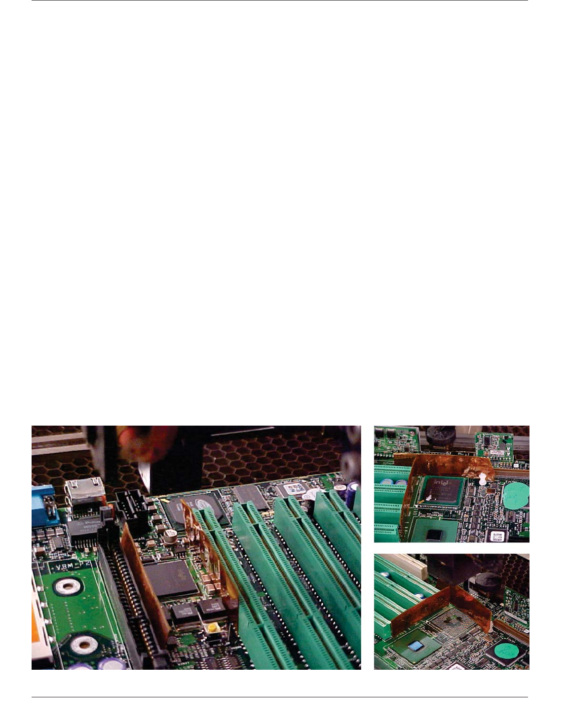
design. See Figure 7-57 for shielding with polyimide tape
to prevent damage to adjacent components when using hot
air for BGA repair.
With lead-free technology, it is recommended to minimize
the temperature delta between the bottom side of the board
and topside of the board during the profiling process for
BGA removal and reattach. The temperature of the bottom
side of the board heating should be increased to minimize
the topside nozzle heat when setting up the profile. This
will minimize exposure of potential delamination of the
bare board or heat transfer to adjacent components.
7.9.3 Replacement
7.9.3.1 Land Pattern Site Dressing
Once the BGA has
been removed from the board, solder will have to be
removed from the land pattern. Solder vacuums and solder
wick works well for removing solder off the lands. Caution
is recommended when using any of these tools because the
land can lift with excessive heat or pressure. Each land
must be completely flat and clean before placing the new
BGA. With the higher temperatures of lead-free alloys, it is
critical to minimize contact with the solder mask dams
between the lands and the vias (dog bone design). The
higher temperatures may increase the potential to damage
this solder mask. It can also be affected by the surface fin-
ish of the bare board. Two variables that can influence the
adhesion of the solder mask to the land are the length of
the solder mask dam (encroached vias are recommended)
and the surface finish of the bare printed boards.
7.9.3.2 Flux Application Although the solder mask
encroached on the via land is over bare copper, adhesion
can be affected when subjected to the surface finish chem-
istry.
Two different methods of flux application can be used:
paste/liquid flux or solder paste; however, using flux only
(in a liquid or paste form) is only applicable for eutectic
BGA reattachment. In addition, some applications require
the addition of solder paste in order to promote a robust
solder joint. If paste flux (also called tack flux) is to be
used ensure that the solder balls are Sn63/Pb37 (eutectic).
Many ceramic BGAs use Pb90/Sn10 solder balls which
reflow at 302°C. If the solder balls are not Sn63/Pb37, then
solder paste has to be used. If solder balls are SN63/Pb37,
Figure 7-57 BGA/Assembly Shielding Examples
IPC-7095C January 2013
114
Copyright IPC-Association Connecting Electronics Industries
Provided by IHS under license with IPC
Not for Resale
No reproduction or networking permitted without license from IHS
--`,,```,,,,````-`-`,,`,,`,`,,`---

then liquid flux or the paste flux are commonly used when
reattaching a BGA, especially BGAs with less than 208
balls. Flux is applied to the land pattern or the BGA solder
spheres and the BGA is placed over it. One drawback of
this method is the coplanarity issue. If the lands are not
perfectly flat, some of the balls may not touch. Excessive
flux application may also cause bridging between solder
balls. With most plastic BGAs the ball alloy will be one
which will reflow into the solder joint.
7.9.3.3 Paste Application Paste application is the pre-
ferred method, but it does add time to the rework process
as well as tooling cost. Paste can be applied locally with
the use of mini-stencils. When ordering mini stencils for
ceramic packages, the same aperture/thickness should be
used as used for initial attach. This will ensure the reliabil-
ity of the ceramic packages for reworked components.
These stencils can be purchased from many different sup-
pliers and are tailored to fit specific land patterns. A fixture
or tape can be used to hold the stencil in place during
application on the land pattern.
When using these methods, considerations have to be made
for solder paste handling and stencil cleaning. Solder paste
can also be applied to the BGA using a syringe or paste
dispensing frame with other proper tooling. The amount of
solder paste applied should be carefully controlled. When
printing solder paste for CSPs, there may not be enough
room on the bare board for mini-stencils. In this situation
it is a common process to screen the solder paste onto the
package (bottom side of the balls) and then place the mod-
ule onto the board for replacement.
7.9.3.4 Rework Issues Interpackage spacing is decreas-
ing constantly. Even if companies have some Design for
Manufacture (DfM) guidelines for interpackage spacing,
those on the front line of manufacturing know very well
that DfM guidelines are not always followed. So, using
mini-stencils to print solder paste is becoming more diffi-
cult. Also, because a mini-stencil is needed for each size
and type of part, it not only slows down the process but
also quickly adds to the cost of repair.
Using a mini-stencil is not the only issue with ever-
decreasing interpackage spacing. Using different hot air
nozzles for each size and type of part being removed also
adds to the cost and complexity of rework. Additionally,
the potential for melting solder joints of neighboring com-
ponents is a serious concern. In addition to increased inter-
metallic thickness because of unnecessary reflow which
weakens the solder joints, the boards must be baked before
rework, increasing cycle time.
Throughput in rework is very important. BGAs and some
of the larger components can take at least 20 minutes per
component for removal and replacement.
Another important issue in rework is PCA board warpage.
Warpage is partly due to intense local heating for a rela-
tively long time, which is necessary to remove the compo-
nent.
For BGA repair, there are two rework processes in use
today: hot air and laser. Hot air is the most common. The
new process for removal and replacement of surface mount
components, including BGAs and CSPs, is laser-based.
Multiple rework on the same BGA site can result in barrel
cracking of the printed wiring board. Consideration must
be made for printed wiring board materials and number of
heat cycles the materials can withstand.
7.9.3.5 Hot Air Systems for BGA Repair Hot air systems
are either totally manual or semi-automated. Using a
nozzle, they blow hot air on the part to be reworked. The
part is pulled away from the board when the solder on all
joints is molten. Bottom-side heating is used to uniformly
heat the entire board to a preheat setting prior to applying
topside nozzle heat, thus reducing thermal shock.The hot
air usually is directed on the BGA package by a nozzle
designed specifically for that component. The package
body is heated by the hot air impinging on the package and
conduction within the package. Initially, the package is
preheated with the nozzle some distance away (typically
25 mm or more) from the package body. Then the nozzle
is lowered to a point just above the package body and lead
temperature increases sharply until it reaches a peak. Dur-
ing this process of blowing hot air, the solder joints of
neighboring components even 12 mm away can reflow, an
unwanted and undesirable result. With higher velocity air,
smaller components such as CSPs are prone to movement
during rework.
After the component is removed, paste application for reat-
tachment is a most difficult and time-consuming process.
However, using flux only (liquid or paste form) is only
applicable for eutectic BGAs reattachment. Some applica-
tions require solder addition to promote a robust joint.
Typically, a mini-stencil or dispenser is used to apply the
paste. Both hot air nozzles and ministencils are needed for
each type and size of part being reworked. Both these items
require sufficient interpackage spacing for rework. The
forced convection heating of the bottom side of the board
will minimize the temperature of the nozzle required to
achieve an acceptable lead-free profile. Typically tin/lead
bottom side preheating is approximately 100°C. This tem-
perature should be increased to 130°C minimum for lead-
free products.
7.9.3.6 Laser Systems for BGA Repair The laser sys-
tems use from one to four diode lasers. Some of the laser
systems are limited to reworking only peripheral compo-
nents, in which the leads are in the laser’s line of sight.
However, there are other laser systems that use multiple
January 2013 IPC-7095C
115
Copyright IPC-Association Connecting Electronics Industries
Provided by IHS under license with IPC
Not for Resale
No reproduction or networking permitted without license from IHS
--`,,```,,,,````-`-`,,`,,`,`,,`---
diode lasers and can rework both peripheral and array type
packages such as BGAs, chip scale packages (CSPs) and
flip chips by rapidly scanning top of package surfaces. This
causes BGA/CSP/flip chip ball to reflow underneath by
conduction through the package, as is the case in hot air
rework. Some of these laser systems also have a built-in
automated thermal management capability to monitor and
control package temperatures within the specified limits to
prevent overheating. There are laser systems with or with-
out dispensing and pick and place capabilities.
Because the laser beam is very narrow, components even
1 mm away do not experience any heat. Laser systems heat
the package without melting the solder joints of neighbor-
ing components.
7.9.3.7 Profile Requirements Whether using laser or hot
air, the reflow profile for a BGA during rework is the same
as the profile for a convection oven. Preheating the board
to 100°C before initiating the removal or replacement cycle
should be sufficient in keeping board warpage to a mini-
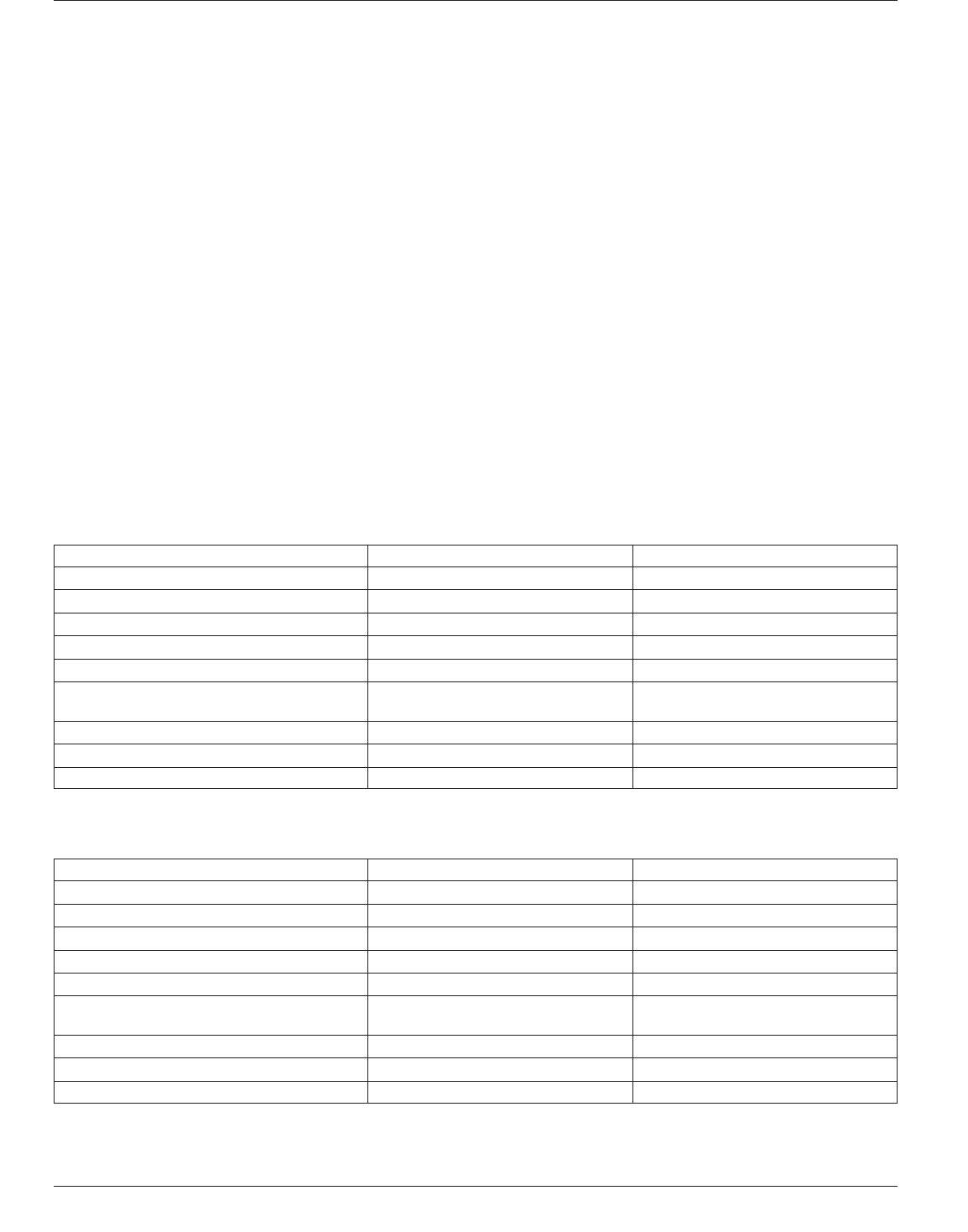
mum. These requirements are summarized in Table 7-9 for
tin lead and 7-10 for lead free. Be careful not to push the
preheat towards 120°C since this is where some fluxes
typically activate. If this happens the flux could be acti-
vated before it is needed and cause poor solderability dur-
ing reflow. For lead-free solder pastes, this preheat tem-
perature should be 120°C to 130°C minimum.
Sufficient time should be allowed for the flux to clean the
ball and the land during the reflow profile. Flux should stay
within 120-150°C for 30 to 120 seconds. After the flux has
cleaned the site, a ramp rate of 2° to 4°C can be used. The
standard 2°C for SMT profiling can be amended since there
should not be any heat sensitive components such as
capacitors or resistors within the reflow nozzle when using
hot air. The components that are adjacent to the nozzle
should be shielded with polyimide tape or water soluble
mask to protect components from thermal damage when
using hot air. The reflow dwell time should be in the range
of 30 to 90 seconds with the solder joint peaking between
200-220°C (for tin/lead) and 235-245°C for lead free. The
balls at the center of the BGA package may exceed the 90
second recommendation due to entrapped heat from the
reflow process. The board temperature should not be kept
above 150°C for any longer than four minutes. This
requirement is due to the glass transition temperature for
FR-4 (see J-STD-020).
Table 7-9 Repair Process Temperature Profiles for Tin Lead Assembly
Profile Topic Temperature Range Time Range
Preheat 100-150°C; not to exceed 150°C N/A
Soak or preheat activation 100-180°C* 60-120 seconds*
Component ramp rate 2-4°C per second
Reflow dwell Above 183°C 60 to 90 seconds
Solder joint peak 210-220°C Not to exceed 10 seconds
A moisture sensitive component maximum
temperature
225°C Not to exceed 20 seconds
Component maximum temperature 230°C 60 seconds
Maximum adjacent component temperature** 170°C 0 seconds
Board temperature Above 150°C Not to exceed four minutes
* Verify with supplier
** Adjacent component equals 5 mm away
Table 7-10 Repair Process Temperature Profiles for Lead-Free Assemblies
Profile Topic Temperature Range Time Range
Preheat 100°C to 190°C; not to exceed 190°C N/A
Soak or preheat activation 140 -220°C* 60 to 150 seconds*
Component ramp rate 2°C to 4°C per second
Reflow dwell Above 220°C 60 to 90 seconds
Solder joint peak 230-245°C Not to exceed 20 seconds
A moisture sensitive component maximum
temperature
245°C Not to exceed 20 seconds
Component maximum temperature 245°C 60 seconds
Maximum adjacent component temperature** 210°C 0 seconds
Board temperature Above 190°C Not to exceed four minutes
* Verify with supplier
** Adjacent component equals 5 mm away
IPC-7095C January 2013
116
Copyright IPC-Association Connecting Electronics Industries
Provided by IHS under license with IPC
Not for Resale
No reproduction or networking permitted without license from IHS
--`,,```,,,,````-`-`,,`,,`,`,,`---