IPC-7095C-2013.pdf - 第83页
physical evaluations that the process and the recipe used to make the part stay in the control that is necessary to meet requirements. This concept is essential for BGAs since one cannot see the lands or the solder joint…

6.5.4.2 In-Circuit Test Concerns In-circuit testing is
used to find shorts, opens, wrong parts, reversed parts, bad
devices, incorrect assembly of printed board assemblies
and other manufacturing defects. In-circuit testing is nei-
ther meant to find marginal parts nor to verify critical tim-
ing parameters or other electrical design functions.
In-circuit testing of digital printed board assemblies can
involve a process that is known as backdriving (see IPC-T-
50). Backdriving can also cause devices to oscillate and the
tester can have insufficient drive to bring a device out of
saturation. Backdriving can be performed only for con-
trolled periods of time, or the junction of the device (with
the overdriven output) will overheat.
The two main concerns for designing the printed board and
printed board assembly for in-circuit testability are design
for compatibility with in-circuit test fixturing and electrical
design considerations.
6.5.4.3 Functional Testing Concerns There are several
concerns for designing the printed board assembly for
functional testability. The use of test connectors, problems
with initialization and synchronization, long counter
chains, self-diagnostics, and physical testing are topics
which are discussed in detail in the following subsections
and are not meant to be tutorials on testability but rather
ideas of how to overcome typical functional testing prob-
lems. Fault isolation on conformal coated boards or most
SMT and mixed technology designs can be very difficult
because of the lack of access to the circuitry on the board.
If strategic signals are brought out to a test connector or an
area on the printed board where the signals can be probed
(test points), fault isolation may be much improved. This
lowers the cost of detection, isolation and correction. It is
also possible to design the circuit so that a test connector
can be used to stimulate the circuit (such as taking over a
data bus via the test connector) or disable functions on the
printed board assembly (such as disabling a free running
oscillator and adding single step capability via the test con-
nector).
6.6 Other Design for Manufacturability Issues The lay-
out generation process should include a formal design
review of layout details by as many affected disciplines
within the company as possible, including fabrication,
assembly and testing. The approval of the layout by repre-
sentatives of the affected disciplines will ensure that these
production-related factors have been considered in the
design. The success or failure of an interconnecting struc-
ture design depends on many interrelated considerations.
From an end-product usage standpoint, the impact on the
design by the following typical parameters should be con-
sidered. Other design for manufacturability issues include:
• Equipment environmental conditions, such as ambient
temperature, heat generated by the components, ventila-
tion, shock and vibration
• If an assembly is to be maintainable and repairable, con-
sideration must be given to component/circuit density, the
selection of board/conformal coating materials, and com-
ponent placement for accessibility
• Installation interface that may affect the size and location
of mounting holes, connector locations, lead protrusion
limitations, part placement, and the placement of brackets
and other hardware
• Testing/fault location requirements that might affect com-
ponent placement, conductor routing, connector contact
assignments, etc.
• Process allowances such as etch factor compensation for
conductor widths, spacings, land fabrication, etc.
• Manufacturing limitations such as minimum etched fea-
tures, minimum plating thickness, board shape and size,
etc.
• Coating and marking requirements
• Assembly technology used, such as surface mount
• Through-hole, and mixed
• Board performance class
• Materials selection
• Producibility of the printed board assembly as it pertains
to manufacturing equipment limitations
– Flexibility (Flexural) Requirements
– Electrical/Electronic
– Performance Requirements
• ESD sensitivity considerations
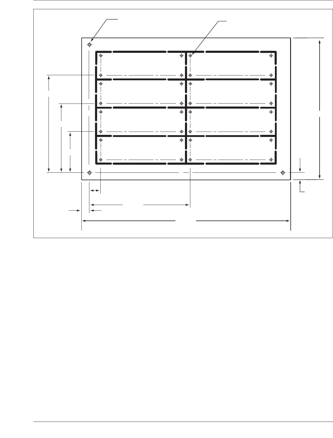
6.6.1 Panel/Pallet Design Panelization of boards and
pallets is a standard process for both test and assembly. A
datum system is required for the fabrication panel, as well
as each individual board or pallet in the panel. To reduce
tolerance buildup, it is important to relate each individual
datum to the panel datum (see Figure 6-31).
Most assembly companies want to build the assembly in
pallet format, similar to that shown in Figure 6-31. The
board manufacturer of these pallets would position them
on the standard fabrication panel, which is usually 460 x
610 mm. Designers are encouraged to work with their
manufacturing suppliers in order to optimize the material
movement, and the manner in which the pallets/boards are
removed from their respective position and how they are
tested.
6.6.2 In-Process/End Product Test Coupons Coupons
have been used by the industry for many years in an effort
to evaluate the product being built. These coupons repre-
sented the features of the board or the features of the
assembly. They are incorporated into the borders of the
panels either used for board manufacturing or the pallets
provided to the assembly company. Most manufacturers
and assemblers have their processes in control, neverthe-
less, coupons are of value to make certain through various
IPC-7095C January 2013
68
Copyright IPC-Association Connecting Electronics Industries
Provided by IHS under license with IPC
Not for Resale
No reproduction or networking permitted without license from IHS
--`,,```,,,,````-`-`,,`,,`,`,,`---
physical evaluations that the process and the recipe used to
make the part stay in the control that is necessary to meet
requirements. This concept is essential for BGAs since one
cannot see the lands or the solder joints once the assembly
has taken place. Test coupons or specimens should reflect
the specific board or panel characteristics. The data derived
from panels should be used to establish the requirements
for vias and lands, conductors, spaces, etc. When speci-
mens are used to establish process control parameters, they
shall consistently use single hole size or land configuration
which reflects the process. Process characteristics and gen-
eral board characteristics should be matched.
IPC-2221 provides excellent coupons that are used to
evaluate those board and assembly characterizations. They
include:
• Hole Solderability
• Solder Resist Tenting
• Thermal Stress Plating
• Thickness and Bond Strength
• Plating Adhesion
• Surface Solderability
• Solder Resist
• Surface Mount Solderability
• Surface Bond Strength
• Surface Insulation Resistance
• Moisture Insulation Resistance
• Registration
• Interconnect Resistance
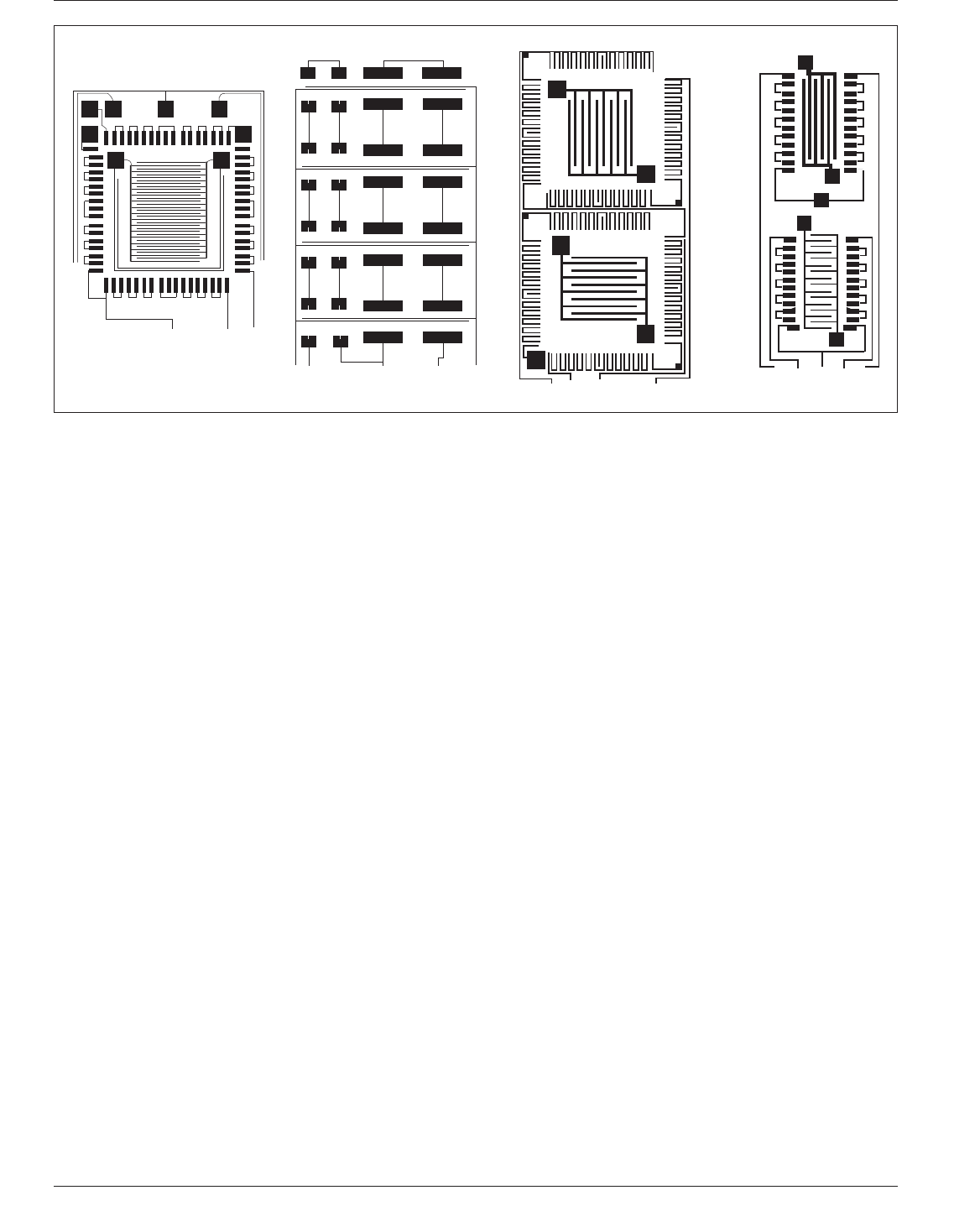
Figure 6-32 shows alternate coupons that can be used to
evaluate the cleanliness of a board after ball attachment has
been completed. These comb patterns are used on the board
in order to make certain that flux or flux residue does not
impair the electrical properties of the product.
6.7 Thermal Management The primary objective of
thermal management is to ensure that all circuit compo-
nents, especially the BGAs, are maintained within both
functional and maximum allowable limits. The functional
temperature limits provide the ambient or component pack-
age (case) temperature range within which the electronic
circuits can be allowed to properly perform.
IPC-7095c-6-31
Figure 6-31 Board Panelization
X.XX
X.XX
X.XXX
X.XXX
X.XXX
X.XX
X.XXX
DATUM
DATUM
X.XXX
X.XX
8 BOARD PANELIZATION
PANEL TOOLING HOLE
(3 PLACES)
INDIVIDUAL BOARD TOOLING HOLES
(3 PLACES PER BOARD)
January 2013 IPC-7095C
69
Copyright IPC-Association Connecting Electronics Industries
Provided by IHS under license with IPC
Not for Resale
No reproduction or networking permitted without license from IHS
--`,,```,,,,````-`-`,,`,,`,`,,`---
The cooling technique to be used in the printed board
assembly applications must be known in order to ensure
the proper printed board assembly design. For commercial
applications, direct-air cooling (i.e., where cooling air con-
tacts the printed board assembly), is usually used.
For rugged and hostile usage, other cooling techniques
must be used to cool the printed board assembly. In this
application, the assembly is mounted to the cooling struc-
ture that is air or liquid cooled, and the board components
are cooled by the conduction through a heat exchange sur-
face. These designs must use appropriate metal heatsinks
on the printed board assembly. Appropriate component
mounting and bonding may be required. To ensure
adequate design, thermal dissipation maps must be pro-
vided to aid analysis and thermal design of the printed
board assembly.
The dissipation of heat generated within electronic equip-
ment results from the interaction of the three basic modes
of heat transfer: conduction, radiation, and convection.
These heat transfer modes can, and often do, act simulta-
neously. Thus, any thermal management approach should
attempt to maximize their natural interaction.
6.7.1 Conduction Conduction takes place to a varying
degree through all materials. The conduction of heat
through a material is directly proportional to the thermal
conductivity constant (K) of the material, the cross-
sectional area of the conductive path and the temperature
difference across the material. Conduction is inversely pro-
portional to the length of the path and the thickness of the
material (see Table 6-11).
6.7.2 Radiation Thermal radiation is the transfer of heat
by electromagnetic radiation, primarily in the infrared (IR)
wavelengths. It is the only means of heat transfer between
bodies that are separated by a vacuum, as in space environ-
ments.
Heat transfer by radiation is a function of the surface of the
‘‘hot’’ body with respect to its emissivity, its effective sur-
face area and the differential to the fourth power of the
absolute temperatures involved.
The emissivity is the ratio of energy radiated by a material
to energy radiated by a black body with an emissivity of
one (1.0) at the same temperature The optical color of a
body has little to do with it being a ‘‘thermal black body.’’
The emissivity of anodized aluminum is the same if it is
black, red or blue. However, surface finish is important. A
matte or dull surface will be more radiant than a bright or
glossy surface (see Table 6-12).
Devices, components, etc. close to one another will absorb
each others’ radiant energy. If radiation is to be the prin-
ciple means of heat transfer, ‘‘hot’’ spots must be kept clear
of each other.
6.7.3 Convection The convection heat transfer mode is
the most complex. It involves the movement of molecules
within a fluid, usually air.
The rate of heat flow by convection from a body to a fluid
is a function of the surface area of the body, the tempera-
ture differential, the velocity of the fluid and certain prop-
erties of the fluid.
The contact of any fluid with a hotter surface reduces the
density of the fluid and causes it to rise. The circulation
resulting from this phenomenon is known as ‘‘free’’ or
‘‘natural’’ convection. The air flow can be induced in this
manner or by some external artificial device, such as a fan
IPC-7095c-6-32
Figure 6-32 Comb Pattern Examples
IPC-7095C January 2013
70
Copyright IPC-Association Connecting Electronics Industries
Provided by IHS under license with IPC
Not for Resale
No reproduction or networking permitted without license from IHS
--`,,```,,,,````-`-`,,`,,`,`,,`---