IPC-7095C-2013.pdf - 第45页
alignment resulting in either a bridge or an open. Another common defect type is opens that fall into the head and pillow category . The primary cause of these open defects is warping and is most often seen in the corner…
increases beyond the T
g
point, the connector will tend to
either bow toward the board, or bow away from the board
(‘‘warp’’). The actual behavior is a function of the connec-
tor geometry, connector material, and the surface tension of
the connector balls to the substrate. Also included in this
analysis are the connector coplanarity requirements for suc-
cessful soldering. The material properties behavior during
reflow and the overall connector size will dictate the con-
nector ball coplanarity requirements. Typically, the copla-
narity requirements of BGA connectors are more stringent
than those of BGA IC packages, due in part to their larger
size.
4.5.3 BGA Materials and Socket Types BGA sockets
are designed to provide the interface between the processor
or other components and the circuit board. These sockets
are primarily made using a glass polymer material that can
withstand a reflow of up to 265°C. One advantage of the
glass polymer material is that it has a CTE approximately
the same as the circuit board. The interface between the
socket and circuit board utilizes BGA technology, but there
are two different designs depending upon the component
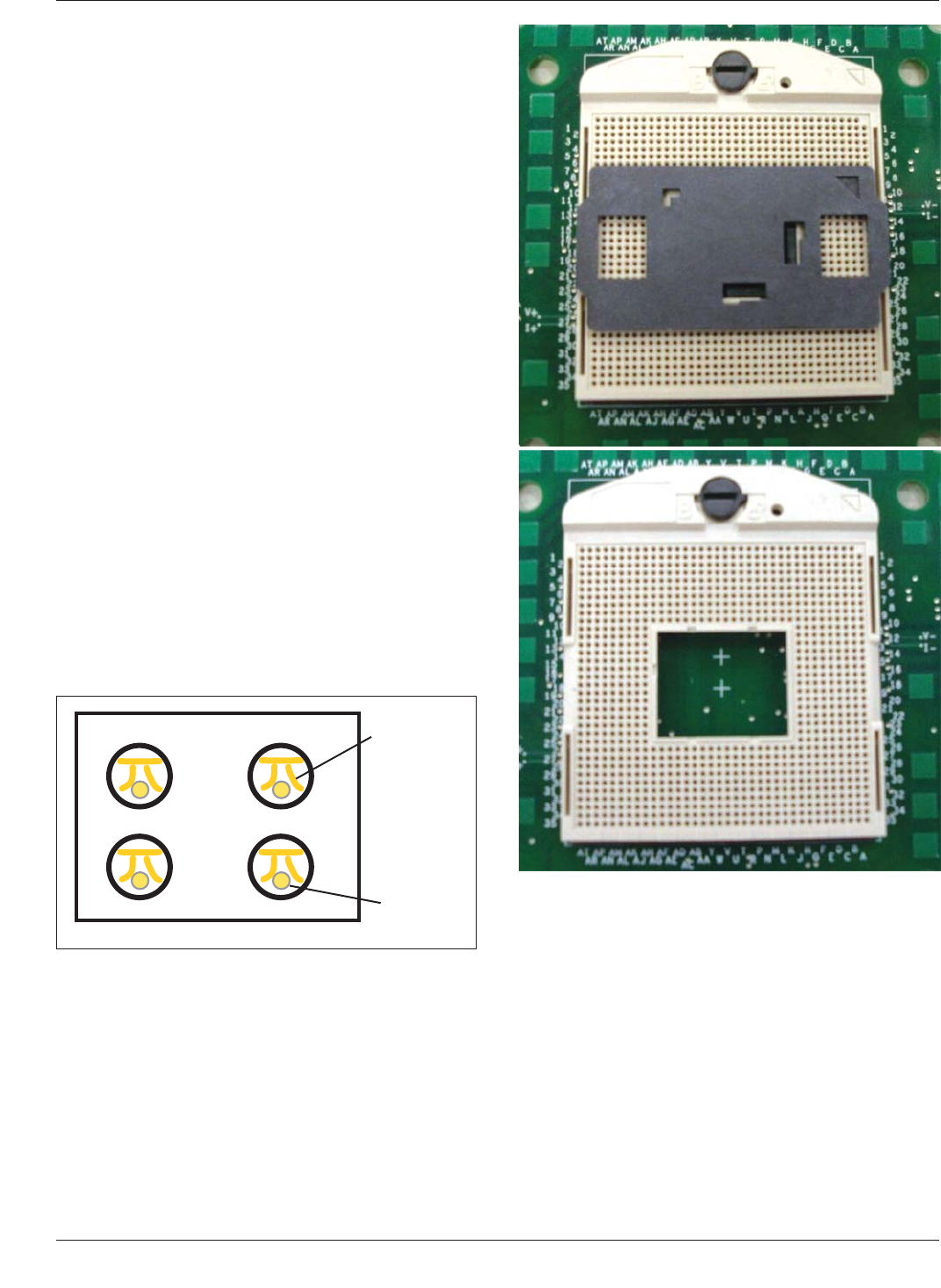
interface of the package they need to mate with. The first
is for Pin Grid Array (PGA) components, the other is for
Land Grid Array components. Sockets for PGA compo-
nents are typically of a zero insertion force type (ZIF) and
utilize a cam nut that moves a cover-plate that the pins
drop through, forward pushing the pins into the contacts
and providing the load needed to make electrical contact
(see Figure 4-23 and Figure 4-24).
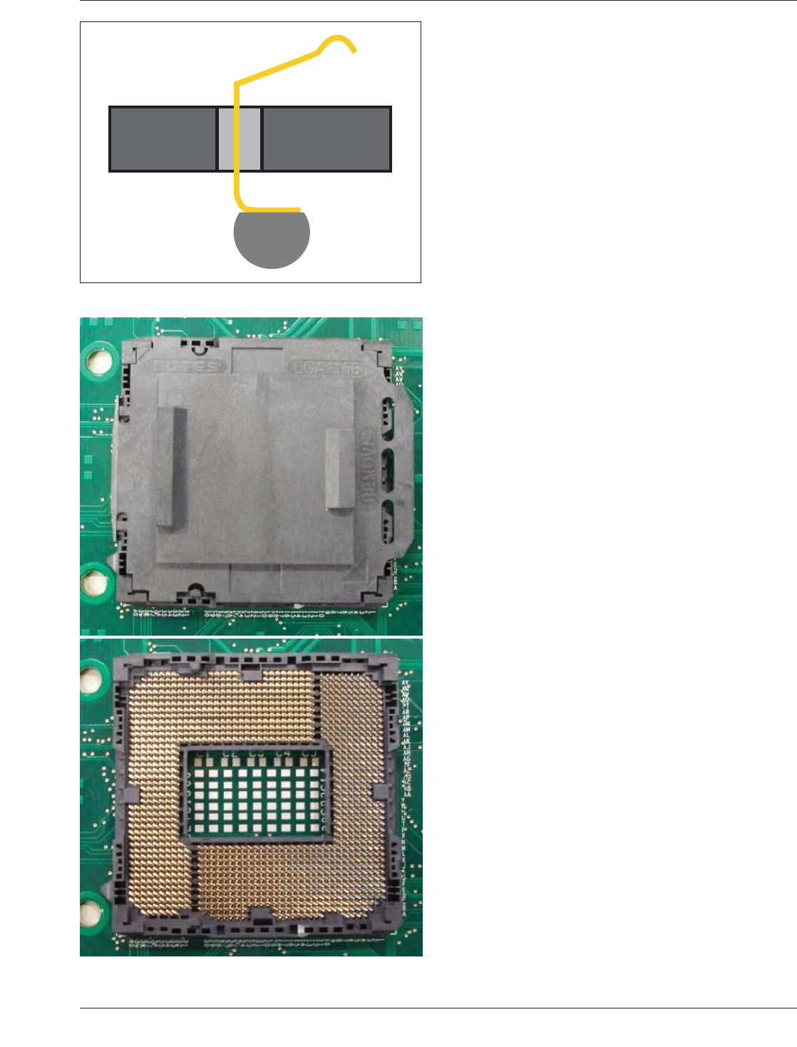
LGA sockets on the other hand use a contact bent at a pre-
cise angle allowing them to contact the land on the pack-
age. The package must have a downward load applied in
order to push the PGA Pin down against the connector
contacts. A loading mechanism is thus required and may be
built into the socket body, or in the case of an Independent
Loading Mechanism (ILM), it is installed after the socket
has been reflowed to the circuit board. The loading mecha-
nism utilizes a lever that when closed applies the necessary
downward force on the component. Both LGA and PGA
socket designs utilize a pick and place cover that snaps
over the socket. These covers serve a dual role of both
protecting the contacts and providing a flat surface for the
placement equipment nozzle to pick them up (see Figure
4-25 and Figure 4-26).
4.5.4 Attachment Considerations for BGA Sockets BGA
sockets have many similar requirements for successful
attachment as those of other BGA components. It is very
important to maintain proper ball coplanarity and control
socket warp before and during reflow. BGA socket han-
dling is even more critical than other BGA components due
to the fact that the solder ball is attached to a paddle and
not directly to a component body or substrate. If bumped,
the paddle can easily be bent, moving the solder ball out of
IPC-7095c-4-23
Figure 4-23 PGA Socket Pins
Socket
contact
PGA Pin
Figure 4-24 PGA Socket With and Without Pick and Place
Cover
IPC-7095C January 2013
30
Copyright IPC-Association Connecting Electronics Industries
Provided by IHS under license with IPC
Not for Resale
No reproduction or networking permitted without license from IHS
--`,,```,,,,````-`-`,,`,,`,`,,`---
alignment resulting in either a bridge or an open. Another
common defect type is opens that fall into the head and
pillow category. The primary cause of these open defects is
warping and is most often seen in the corner balls of the
socket. Besides having a socket that remains relatively flat
during reflow, there are several steps that can be taken to
mitigate the effect.
Processor sockets have an opening in the center to allow
for capacitors on the bottom side of the component.
Because the socket is covered by the pick and place cap,
this creates somewhat of a dead air space during reflow
causing the solder balls closest to the cavity to be cooler
than those on the outer rows. It is, therefore, important that
close attention is paid to the reflow profile minimizing the
temperature delta between the inner and outer solder balls.
Lowering the temperature delta will help minimize the
socket warp during reflow. Another step to reduce opens is
to increase the solder paste volume particularly in the areas
having the issue. It is not always practical to increase the
stencil thickness, so increasing the size of the stencil aper-
ture may be an alternative. As always, it is best to follow
the solder paste manufacturer’s recommendation when cre-
ating a reflow profile; but making sure the maximum tem-
perature, soak time, and time above liquidus are not at the
lower end can also help avoid head and pillow opens.
4.6 BGA Construction Materials
4.6.1 Types of Substrate Materials
A number of differ-
ent materials are used in the construction of BGAs. The
material choice is predicated on a number of different fac-
tors including cost, use environment, reliability require-
ments, etc. The material choice is also dependent on the
processes used in the manufacture of the BGA and the
complexity of the design required to redistribute the chip
I/O to area array format. Base materials are selected not
only by their electrical characteristics, but also their
mechanical properties. Most component manufacturers
require that the material used to redistribute the I/Os meet
a stress test identified in the JEDEC standard, JESD22, Test
Method A102B. The test consists of an exposure in a pres-
sure vessel for 168 hours. This severe accelerated stress
test permits the use of only the most robust materials for
the substrate interposer.
4.6.1.1 Bismaleimide Triazine-Glass (BT) Bismaleimide
triazine resins used in combination with glass fabric rein-
forcements are a common choice for the fabrication of sub-
strates used in BGA packages. The material is available
from a number of sources and provides good thermal per-
formance (based on a relatively high glass transition tem-
perature). In addition, the electrical properties of BT resin
(IPC-4101/30 with a T
g
range of 170-220°C) are suitable
for a great number of IC package applications.
IPC-7095c-4-25
Figure 4-25 LGA Contact Pin
Figure 4-26 LGA Socket With and Without Pick and Place
Cover
January 2013 IPC-7095C
31
Copyright IPC-Association Connecting Electronics Industries
Provided by IHS under license with IPC
Not for Resale
No reproduction or networking permitted without license from IHS
--`,,```,,,,````-`-`,,`,,`,`,,`---

4.6.1.2 Epoxy-Glass (FR-4) A fire retardant epoxy-glass
composite can be used for BGA package applications but
the material is most commonly used in the manufacture of
printed circuits. High T
g
FR-4 laminates (tetra-functional,
multi-functional) have been predominantly used in manu-
facturing multilayer circuit boards; but the material may be
suitable for BGA packaging as well. Recent advances in
the epoxy-resin material formulation have resulted in
greatly improved high temperature performance and rivals
BT in terms of glass transition temperature. Another advan-
tage of using FR-4 resin systems for BGA construction is
that they are more closely matched in CTE to the circuit
board onto which they are mounted. IPC-4101 has under-
gone extensive expansion to meet RoHS compliance and
the requirements of lead-free soldering. The compositions
have been formulated to minimize both the rate of decom-
position and excessive Z axis expansion during soldering
processes (processes that may exceed 260°C). Because
manufacturers use widely varying compositions to manu-
facture epoxy-glass base material, a single slash sheet
specification is not practical. Six specifications that are
RoHS compliant are IPC-4101/99, /101, /121, /124, /126
and /129. There are only slight differences in composition
elements with a T
g
range between 110°C and 170°C and a
decomposition (T
d
) range between 310°C and 340°C. All
have a UL flammability rating of V-O (see Table 4-8).
4.6.1.3 Fire retardants for FR-4 In regard to the fire-
retardant used in manufacturing FR-4 composites, the
RoHS directive forbids the use of some bromine com-
pounds, but it does not ban brominated materials used
currently as a flame retardant for glass reinforced base
materials used for substrate fabrication. Bromine-
containing compounds that are outlawed by RoHS are
those that remain as independent molecules within the
polymeric matrix. These include polybrominated diphenyl
ether (PBDE) or polybrominated biphenyl oxide (PBBO)
and polybrominated biphenyls (PBB). Bromine-containing
compounds that are compliant with RoHS include those
that react to become a chemical part of the polymeric
matrix, for example, tetrabromobisphenol A (TBBPA).
Being RoHS compliant does not mean the base material
must be halogen free. Certain brominated flame retardants
including the most popular brominated flame retardant for
FR-4, TBBPA, are accepted by RoHS and decabromodi-
phenyl ether (DBDPE) has been given an exemption by
RoHS.
4.6.1.4 Ceramic Ceramic is the term used for a general
class of substrate based on alumina or aluminum oxide.
The material is one of the first used for area array packag-
ing in the form of pin grid arrays and was also the material
first used in the construction of the earliest BGA packages.
Ceramic substrates have higher thermal conductivity and,
using a cavity and lid format, can provide hermetic pack-
aging capability. Ceramic substrate material does, however,
have a number of detractors. For example, it is normally
more expensive, more brittle, has a higher dielectric con-
stant (which retards signal propagation speed) and has a
coefficient of thermal expansion much lower than the typi-
cal circuit board structure onto which it is normally
mounted. This last point is a major concern and can limit
the overall package size and the need to maximize the ball
contact size in order to achieve acceptable solder joint reli-
ability of the assembled package.
4.6.1.5 Flexible (Non-Reinforced) Base Films Flexible
base films are an increasingly common choice for BGA
construction. The most common base film for such con-
structions is polyimide. Polyimide has a number of attrac-
tive attributes, which make it a strong choice for BGA
substrates. Among the positive attributes offered by
Table 4-8 IPC-4101C FR-4 Property Summaries - Specification
Sheets Projected to Better Withstand Lead-Free Assembly
Property
IPC-4101B Specification Sheets
/99 /101 /121 /124 /126 /129
T
g
min (°C) 150 110 110 150 170 170
T
g
max (°C) N/A N/A N/A N/A N/A N/A
Td min (°C) 325 310 310 325 340 340
Fillers yes yes no no yes no
Flame Retardant RoHS BR RoHS BR RoHS BR RoHS BR RoHS BR RoHS BR
Flammability V-0 V-0 V-0 V-0 V-0 V-0
Max Z-Axis CTE - alpha 1 60 60 60 60 60 60
Max Z-Axis CTE - alpha 2 300 300 300 300 300 300
Max Z-Axis CTE (50-260°C) 3.5 4.0 4.0 3.5 3.0 3.5
T-260 (minutes) 30 30 30 30 30 30
T-288 (minutes) 5 5 5 5 15 15
T-300 (minutes) AABUS AABUS AABUS AABUS 2 2
UL Max. Operating Temp (°C) AABUS AABUS AABUS AABUS 130 130
IPC-7095C January 2013
32
Copyright IPC-Association Connecting Electronics Industries
Provided by IHS under license with IPC
Not for Resale
No reproduction or networking permitted without license from IHS
--`,,```,,,,````-`-`,,`,,`,`,,`---