IPC-7095C-2013.pdf - 第133页
8.1.5 Mechanical reliability Mechanical reliability refers to the response of the BGA interconnect to a mechanical stimulus. These stimuli include shock events, which may occur during shipping, installation, or field use,…

Comparing SAC lead-free solder joint with SnPb solder
joint, there are distinct intrinsic differences in their respec-
tive metallurgy that determines their dislocation systems,
microstructures and metallurgical phases, which in turn
dominate the fatigue behavior and degradation mechanism
in response to various service conditions, and thus the
fatigue life.
It should be noted that stresses acting upon solder joints in
real world applications are usually random in nature rather
than ‘‘regularly’’ cyclic as the commonly used parameters
in an ATC (accelerated temperature cycling) test. One chal-
lenge is to extrapolate from cyclic test data to the behavior
under actual random stresses. Based on the underlying met-
allurgy, this challenge escalates in SAC lead-free system in
comparison with tin/lead eutectic.
In practical terms, a fatigue phenomenon involves chance,
randomness, and probability. This is why one simple ATC
test is hardly able to determine a conclusion. And it stands
to reason that the test data should be in congruence with
the principles of science and needs to be checked-and-
balanced with the underlying scientific principles; in this
case, the fundamental metallurgy and fracture mechanics.
8.1.3 Creep Additionally, soft solders, even under ambi-
ent temperatures (298 ± 5°K), reach a homologous tem-
perature well beyond 0.5. Therefore, creep behavior is also
expected to occur, which complicates the overall degrada-
tion behavior and failure mechanism, as the creep and
fatigue processes operate interactively. In contrast to
fatigue, solder creep is defined as a time-dependent defor-
mation, which is irreversible and global.
When a stress is applied and sustained, solder responds
with an instantaneous strain in the elastic and/or plastic
region. As time progresses, solder may continue to deform
in a time-dependent manner and eventually fail. Theoreti-
cally, this time-dependent deformation can occur at a tem-
perature above the absolute zero, albeit very slowly. In the
low temperature region, the creep strain is very limited and
deformation normally does not lead to eventual rupture.
The strain accumulates in a logarithmic rate. In the high
temperature region, the creep curve departs from the loga-
rithmic relationship.
A typical creep curve (deformation vs. time) comprises
three stages: primary, secondary and tertiary. In the primary
stage, the transient strain rate decreases rapidly from a very
large initial value due to structural alterations when a sol-
der deforms. The secondary creep prevails at the tempera-
ture above the half of the alloy’s melting temperature and
correlates well with the self-diffusion process. The disloca-
tion climb or glide is generally considered to be the rate-
determining step. The creep rate in this stage reaches a
steady state, as a result of a balance between two compet-
ing metallurgical processes—strain hardening and recovery
(a softening effect). The more the solder is plastically
deformed, the more difficult it becomes to continue the
deformation. The work hardening operates through the
generation and the interaction between dislocation defects
acting as obstacles to further the deformation process. At
higher temperatures, work hardening may be partially or
fully counteracted by recovery. Under this condition, a
time-dependent, thermally-activated, strain-energy-
releasing softening process occurs. The deformation
reaches a dynamic steady state in which the rate of work
hardening is equal to the rate of recovery.
When the softening effect and rising stress overcome the
strain hardening, the tertiary stage sets in, where the creep
rate accelerates until the rupture occurs. This stage is nor-
mally associated with structural changes such as the onset
of recrystallization, coarsening and formation of internal
cracks and/or voids that are precursors to fracture.
Separately, each of these two phenomena is associated and
controlled by a different set of parameters in microstruc-
tural as well as atomic-level material properties.
8.1.4 Creep and Fatigue Interaction Solder joints in the
real world performance of electronics are exposed to the
conditions that induce both fatigue and creep processes and
they operate interactively. Simply put, this environment can
be considered as creep under cyclic thermal loading or
fatigue under high temperature. This interactive nature
between creep and fatigue complicates the solder joint deg-
radation behavior and the underlying failure mechanism.
Thus, the solder joint intrinsic degradation leading to an
eventual failure can hardly be a creep failure or a fatigue
failure, rather is the result of interactive fatigue and creep.
And the mechanisms of creep and fatigue are expected to
operate in a competitive, alternative or mutually promoting
manner, depending on the service conditions that combine
both the external climate and the in-circuit operation envi-
ronment. In the commonly adopted Accelerated Tempera-
ture Cycling test, the creep and fatigue processes also oper-
ate interactively. From an engineering perspective, one can
consider the degradation phenomenon as either creep-
aggravated fatigue or fatigue-accelerated creep.
Reliability is a relative term. The system’s operating con-
ditions must be specified and its functional period of time
be also specified. In engineering, reliability is the probabil-
ity that a system will perform a required function without
failure under a given set of conditions for an intended
period of time. Weibull distribution, a continuous probabil-
ity distribution has been widely used in reliability engineer-
ing and failure analyses. As the Weibull plot is one conve-
nient method of calculating the parameters of the Weibull
distribution, almost all publications related to lead-free reli-
ability include the Weibull plot, which plots empirical
cumulative distribution of data: time-to-failure.
IPC-7095C January 2013
118
Copyright IPC-Association Connecting Electronics Industries
Provided by IHS under license with IPC
Not for Resale
No reproduction or networking permitted without license from IHS
--`,,```,,,,````-`-`,,`,,`,`,,`---

8.1.5 Mechanical reliability Mechanical reliability refers
to the response of the BGA interconnect to a mechanical
stimulus. These stimuli include shock events, which may
occur during shipping, installation, or field use, transient
bend, which may occur during manufacturing (in-circuit
test, functional test, installation, etc.) or in the field, cyclic
bend, such as repetitive keystrokes near a BGA, or vibra-
tion due to fans, or motors near or in the system. All of
these stimuli, and others, can have an effect on the
mechanical integrity of the BGA interconnect, and all of
them should be considered when using BGAs, which are
particularly susceptible to flexure based stressors.
8.1.5.1 Shock A shock event is characterized by signifi-
cantly high-speed, which does not allow time for intercon-
nect materials to respond to the applied force. Shock can be
induced via drop or impact, and can occur at any time dur-
ing the life of the product, although shipping and end-user
environment shock events are most typical. Shock events
can result in a separation, either partial or full, of a BGA
interconnect, at any of the interfaces making up the full
interconnect attachment. Even a partial interfacial fracture
can eventually, over the life of a product, cause an electri-
cal failure in a BGA. More brittle materials and interfaces
are particularly susceptible to shock induced failures.
8.1.5.2 Transient Bend Transient bend, or flexure, is
characterized by a low number (typically 1-10 flexure
events) of relatively slow strain. These events can be
induced during manufacturing, especially in test fixtures
such as ICT or functional testers that use pogo-pin style
probes, during connector insertion, or screw-down of the
PCA into a chassis. Transient bend can also be induced
during unit repair, shipping, and in the end-user environ-
ment. As with shock, these failures typically occur at an
interconnect interface and can result in either a complete
open, or a latent field risk as partial fractures can eventu-
ally open in the field.
8.1.5.3 Cyclic Bend Cyclic bend is typified by multiple
relatively low-level strain events. These events can run into
the thousands or above, and are usually caused by repeti-
tive actions such as keypad actuation, transportation, and
connector insertion or extraction (such as in notebook
docking stations). Over time, fatigue failures may result.
8.1.5.4 Vibration Vibration is characterized by a con-
tinuous low-amplitude displacement of relatively high fre-
quency (as compared to the other mechanical stresses
described above). Vibration can impinge on a BGA due to
proximity of the component to a vibrating subsystem, such
as a motor, fan, or disk drive. It is possible, if the intercon-
nect system has already been stressed to the point of inter-
facial fracture, that vibration may exacerbate the issue,
leading to an electrical open; however, this is not yet well
understood.
8.2 Damage Mechanisms and Failure of Solder Attach-
ments
The reliability of an electronic assembly depends
on the reliability of the sum of the individual elements of
the mechanical thermal and electrical interfaces (or attach-
ments) between these elements. One interface type, the sur-
face mount solder attachment, is unique since the solder
joint not only provides the electrical interconnection, but is
also the sole mechanical attachment of the electronic com-
ponents to the printed board. It often provides the critical
heat transfer function as well. A solder joint in isolation is
neither reliable nor unreliable; it becomes so only in the
context of application.
The characteristics of these three elements—component,
substrate, and solder joint—together with the use condi-
tions, the design life, and the acceptable failure probability
determine the reliability of the surface mount solder attach-
ment.
The general characteristics of most lead-free solders as
compared to tin/lead solders, include (1) significantly
increased alloy stiffness, (2) significantly slower creep
rates, (3) greater difficulties of proper spread, and (4) sig-
nificantly higher soldering temperatures.
The consequence of the greater stiffness or lower ductility
and the slower creep rates are higher stresses on the whole
solder attachment structure during either temperature
changes, causing thermal expansion mismatches or PCB/
component warping, or bending. These higher stresses,
combined with less strong solder to base material connec-
tions due to inadequate wetting or interfacial structural
weaknesses, may cause brittle interfacial failure.
8.2.1 Comparison of Thermal Fatigue Crack Growth
Mechanism in SAC vs. Tin/Lead BGA Solder Joints
Eutectic tin/lead solder joints develop different damage
mechanisms than SAC BGA solder joints during Thermal
Fatigue Tests, such as Temperature Cycling. Eutectic tin/
lead solder microstructure is multi-grained, with each BGA
solder joints having many individual grains of lead-rich
(dark phase) and tin-rich (light colored phases) precipitated
out, as seen in Figure 8-1. In contrast, each SAC BGA sol-
der joint has very few grains of tin. These grains can be
seen under cross-polarizing light. Figure 8-2 shows two
examples of SAC BGA solder joints. The one on the left
has 6 grains, whereas the entire solder joint on the right is
comprised of a single grain.
January 2013 IPC-7095C
119
Copyright IPC-Association Connecting Electronics Industries
Provided by IHS under license with IPC
Not for Resale
No reproduction or networking permitted without license from IHS
--`,,```,,,,````-`-`,,`,,`,`,,`---
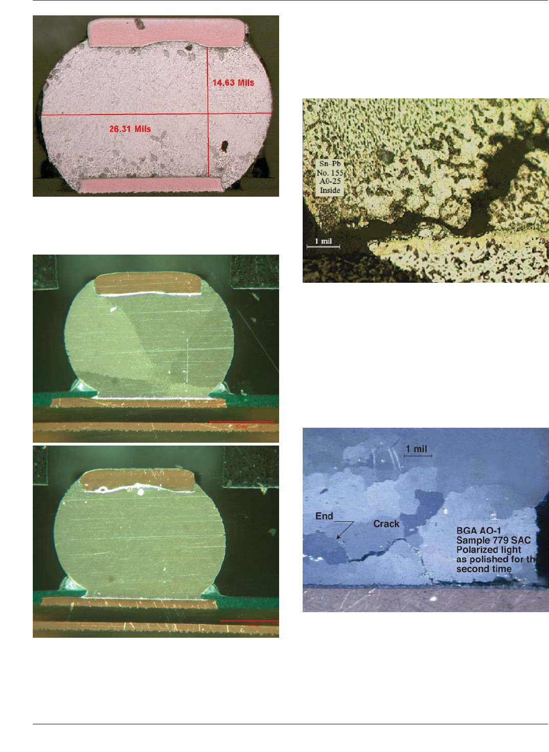
For eutectic tin/lead BGA solder joints, during temperature
cycling, grain coarsening occurs in areas of the solder joint
where the strains due to thermal mismatch build up. These
coarser grains are softer than the original as solidified
grains, and promote crack propagation. This is shown in
Figure 8-3.
For lead-free SAC BGA solder joints, when subjected to
thermal cycling, re-crystallization of grains takes place in
regions of large thermo-mechanical stress. These
re-crystallized grains are smaller in size than the original
grains and are more prone to grain boundary sliding and
hence creep deformation. This causes the fatigue cracks to
propagate through this re-crystallized region, as shown in
Figure 8-4.
Figure 8-1 BGA Solder Joint of Eutectic Tin/Lead Solder
Composition Exhibiting Lead Rich (Dark) Phase and Tin
Rich (Light) Phase Grains
Figure 8-2 Socket BGA Solder Joints of SnAgCu Compo-
sition, Showing the Solder Joint Comprised of 6 Grains
(Top Photo) and a Single Grain (Bottom Photo).
Figure 8-3 Thermal-Fatigue Crack Propagation in Eutectic
Tin/Lead Solder Joints in a CBGA Module
Figure 8-4 Thermal-Fatigue Crack Propagation in
Sn-3.8Ag-0.7Cu Joints in a CBGA Module
IPC-7095C January 2013
120
Copyright IPC-Association Connecting Electronics Industries
Provided by IHS under license with IPC
Not for Resale
No reproduction or networking permitted without license from IHS
--`,,```,,,,````-`-`,,`,,`,`,,`---