IPC-7095C-2013.pdf - 第36页
4.3.5 Package-on-Package BGA The package-on- package (PoP) innovations are proving to be preferred for a broad range of SiP applications. User companies have realized that complex mixed-technology functions can be produc…

Although not mandatory, nonsymmetrical ball patterns
have the added advantage of enabling automated orienta-
tion detection during assembly. One example is to omit one
of the corner balls in an otherwise symmetrical array.
4.3.2.1 Future Ball Contact Size Conditions Although
not required for the BGAs shown in Table 4-2, future ball
sizes contemplated are shown in Table 4-3.
4.3.2.2 Land Pattern Approximation The land pattern of
the component substrate (where the ball is attached) and
the land pattern of the mounting structure (printed board)
should be as similar in diameter as possible. Component
manufacturers have determined that the printed board land
pattern or the pad on the component should be slightly less
than the ball diameter. The amount of reduction is based on
the original ball size, which is used to determine the aver-
age land. In determining the relationship between nominal
characteristics, a manufacturing allowance for land size has
been determined to be 0.1 mm between the maximum
material condition (MMC) and least material condition
(LMC) for ball diameters of 0.40 mm and above and less
for balls that are smaller.
The information shown in Table 4-4 provides data on land
patterns and their variation to accommodate nine ball
diameters.
Many component manufacturers use solder mask-defined
lands (see 6.2.2). When this technique is employed, the
nominal land diameter should be increased by the amount
of solder mask encroachment on the land (usually about
0.1 mm). The opening in the solder mask window then
represents the diameter to which the ball will become
attached, while the actual land is slightly larger to accom-
modate the solder mask-defined land concepts. It should be
noted that routing density is decreased, since the land is
larger.
4.3.3 BGA Package Outline Body sizes for ball grid
arrays are divided up into the following two outline groups:
square and rectangular. The square outline package family
size ranges from as small as 4 mm x 4 mm and as large as
50 mm x 50 mm. In the fine pitch variations, the package
sizes increase in 1.0 mm increments. In the ranges above
21 mm x 21 mm, the body size increases in increments of
2.0 mm to 2.5 mm and the pitches are in the regular range.
Rarely will any of the fine pitch parts be found in sizes
larger than 21 mm x 21 mm. The rectangular BGA family
has the same size ranges from 4.0 mm to 50 mm but varies
by each application. This group can have many more varia-
tions than the square group. Rectangular sizes typically are
found to follow no fixed incremental progression. This
group is normally driven by the memory applications and
closely follows the die sizes. Rectangular sizes are nor-
mally standardized in small application specific families.
The fine pitch BGA components, equal to or less than 0.8
mm, rarely exceed 21 mm in body size.
A fine pitch ball grid array (FBGA) is a 0.50 to 0.80 mm
pitch solder balled array package that have fixed package
dimensions ‘‘D (Length)’’ and ‘‘E (Width).’’ The FBGA is
more like the plastic and ceramic BGA families described
above having fixed body dimensions. Although the FBGA
outline is typically only 20% larger than the die, it will not
change shape with every die shrink.
The die-size ball grid array package (DSBGA) is a 0.30 to
0.50 mm pitch solder balled array package that has variable
package dimensions ‘‘D (Length)’’ and ‘‘E (Width).’’ The
DSBGA package takes the shape of the die which normally
makes it a rectangular outline and is presently widely used
in Flash and DRAM Memory devices. The rectangular die
size (RDS) outline will likely change ‘‘D’’ and ‘‘E’’ dimen-
sions with every die shrink.
4.3.4 Ball Size Relationships The total variation of the
system considers three major issues: positioning, ball toler-
ance, and substrate tolerance. All three attributes added
together result in a worst case analysis; however, as with
other land patterns in the standard, a statistical average is
determined by using the RMS (root mean, square) value.
The trend toward higher pin-count ICs and smaller package
outlines has enabled companies to improve both product
functionality and performance. Table 4-5 will assist the
user in calculating variations in land pattern geometry for a
wide range of BGA applications, and shows the total varia-
tion in the system for each of the nine ball sizes identified
in the standards. As noted, the standard nominal dimension
for ball contact diameters are 0.15, 0.20, 0.25, 0.30, 0.40,
0.45, 0.50, 0.60, and 0.75 mm. Ball contact size for array
packages are influenced by the limit established for overall
package height, ball contact pitch and the desire to maxi-
mize solder joint reliability.
Table 4-3 Future Ball Size Diameters for DSPBGAs
Nominal Ball
Diameter (mm)
Tolerance
Variation (mm) Pitch (mm)
0.25 0.28 - 0.22 0.40
0.20 0.22 - 0.18 0.30
0.15 0.17 - 0.13 0.25
Table 4-4 Land Size Approximation
Nominal Ball
Diameter (mm) Reduction
Nominal Land
Diameter (mm)
Land
Variation (mm)
0.75 25% 0.55 0.60 - 0.50
0.60 25% 0.45 0.50 - 0.40
0.50 20% 0.40 0.45 - 0.35
0.45 20% 0.35 0.40 - 0.30
0.40 20% 0.30 0.35 - 0.25
0.30 20% 0.25 0.25 - 0.20
0.25 20% 0.20 0.20 - 0.17
0.20 15% 0.15 0.15 - 0.12
0.15 15% 0.10 0.10 - 0.08
January 2013 IPC-7095C
21
Copyright IPC-Association Connecting Electronics Industries
Provided by IHS under license with IPC
Not for Resale
No reproduction or networking permitted without license from IHS
--`,,```,,,,````-`-`,,`,,`,`,,`---
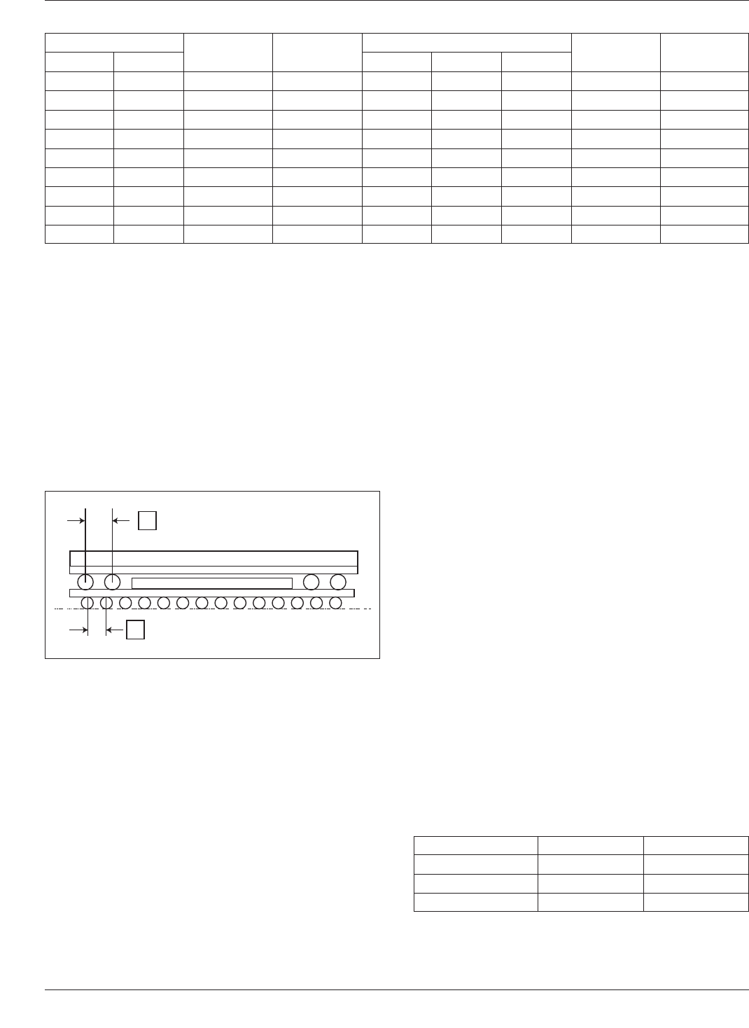
4.3.5 Package-on-Package BGA The package-on-
package (PoP) innovations are proving to be preferred for
a broad range of SiP applications. User companies have
realized that complex mixed-technology functions can be
produced with higher yield and more economically if the
semiconductors are individually prepackaged and tested
before joining. The most common solution for PoP appli-
cations utilizes package sections designed around the exist-
ing JEDEC FBGA standard array packaging format (see
Figure 4-5). Stacking prepackaged die has less risk because
the individual packages are fully tested before conversion
to the stacked PoP format.
Whether or not to join one package to the other before or
during the board level assembly process is a decision that
may be influenced by the requirement for in-process con-
figuration flexibility. For example, the base package can be
furnished by vendor ‘‘A’’ while the memory sections of the
stack are supplied by vendor ‘‘B,’’ ‘‘C’’ or ‘‘D.’’ After all,
memory functions are available from a greater number of
sources and the testing for memory is somewhat special-
ized. Furthermore, the concern of ownership of total qual-
ity and reliability can be alleviated. The logic device sup-
plier is responsible for the logic, the memory
manufacturers are responsible for the respective memory,
and the board assembler is responsible for only the surface
mount attachment of the two. This alternative has two ben-
efits. It allows the user to specify multiple variations (dif-
ferent memory functions, data rate and so on) as well as
accommodating secondary sources of supply.
4.3.6 Coplanarity A critical issue in surface mount
packages is the limits for coplanarity of the contacts. The
coplanarity requirements in a BGA package are very differ-
ent from other lead-frame packaged surface mount compo-
nents. Coplanarity for any BGA is the distance of compo-
nent contact surface above a common seating plane. Thus
noncoplanarity, a simplified term, is the maximum distance
between the lowest and the highest contact when the pack-
age rests on a perfectly flat surface. This definition repre-
sents a package sitting on a PC board on at least three
locations.
Coplanarity tolerance defines the distance from the seating
plane to the highest point of the package. This dimension
includes the standoff height, package body thickness and
(if present) lid thickness. The measurement criteria do not
include attached features such as heat sinks or other com-
ponents. An integral heat-slug, however, is not considered
an attached feature. If the package happens to be laminate
substrate based BGA, additional coplanarity issues can be
expected due to problems associated with adapting larger
substrates and maintaining flatness within the tolerances.
This, in part, is the reason why the plastic BGA (PBGA)
package coplanarity requirement is established at 150 µm.
Most suppliers would like the allowable BGA coplanarity
limit to be around 200 µm but the users would prefer the
maximum to be no greater than 100 µm (see 4.6.2.6 and
4.8.4). There are different coplanarity requirements for dif-
ferent types of BGAs. Table 4-6 shows a sampling of
JEDEC registered BGA package outlines.
The coplanarity values may vary from JEDEC outline-to-
outline because of the ball metallurgy. In low temperature,
eutectic (183°C melting point) solder balls, the balls
Table 4-5 Land-to-Ball Calculations for Current and Future BGA Packages (mm)
Land Size
Location
Allowance
Ball
Variation
Ball Size
% Reduction
from Nom.
Variation
AllowanceMMC LMC Nominal MMC LMC
0.60 0.50 0.10 0.25 0.75 0.90 0.65 25% 0.25
0.50 0.40 0.10 0.20 0.60 0.70 0.50 25% 0.20
0.45 0.35 0.10 0.10 0.50 0.55 0.45 20% 0.17
0.40 0.30 0.10 0.10 0.45 0.50 0.40 20% 0.17
0.35 0.25 0.10 0.10 0.40 0.45 0.35 20% 0.17
0.25 0.20 0.05 0.10 0.30 0.35 0.25 20% 0.15
0.20 0.17 0.05 0.06 0.25 0.28 0.22 20% 0.08
0.15 0.12 0.05 0.04 0.20 0.22 0.18 15% 0.07
0.10 0.08 0.05 0.04 0.15 0.17 0.13 15% 0.07
IPC-7095c-4-5
Figure 4-5 JEDEC Standard Format for Package-on-
Package Components Source: JEDEC Publication 95-4.22
e
= 0.65 mm
0.50 mm
e
=
0.65 mm
0.80 mm
0.50 mm
Table 4-6 Examples of JEDEC Registered BGA Outlines
Registered Outline Package Type Coplanarity
MO-151 Plastic BGA 0.20 mm
MO-156/MO-157 Ceramic BGA 0.15 mm
MO-195 Fine Pitch BGA 0.08 mm
IPC-7095C January 2013
22
Copyright IPC-Association Connecting Electronics Industries
Provided by IHS under license with IPC
Not for Resale
No reproduction or networking permitted without license from IHS
--`,,```,,,,````-`-`,,`,,`,`,,`---
collapse during the assembly operation; therefore, the
coplanarity requirement is not as tight as a high tempera-
ture (302°C melting point) solder balls in which the balls
do not collapse during the assembly operation.
4.4 Component Packaging Style Considerations The
JEDEC Design Guidelines for BGA do not define specific
materials or method of assembly. The base material will
vary from one supplier to another depending on applica-
tion. The base structure is most likely a reinforced organic
laminate, a nonreinforced polyimide film or ceramic.
Ceramic-based BGA packages are often supplied with non-
collapsing solder balls made of high temperature solder
(90% lead, 10% tin) with a melting point of 302°C. The
ball size will vary with the pitch and package size. Larger
packages will usually have larger ball sizes to improve
reliability. Since the ceramic package is relatively very flat
and the tolerances in ball diameters are very narrow, the
coplanarity requirements can be relatively narrow as well.
The supplier of the ceramic-based package will generally
furnish recommendations for selecting a suitable solder
paste composition for board level assembly.
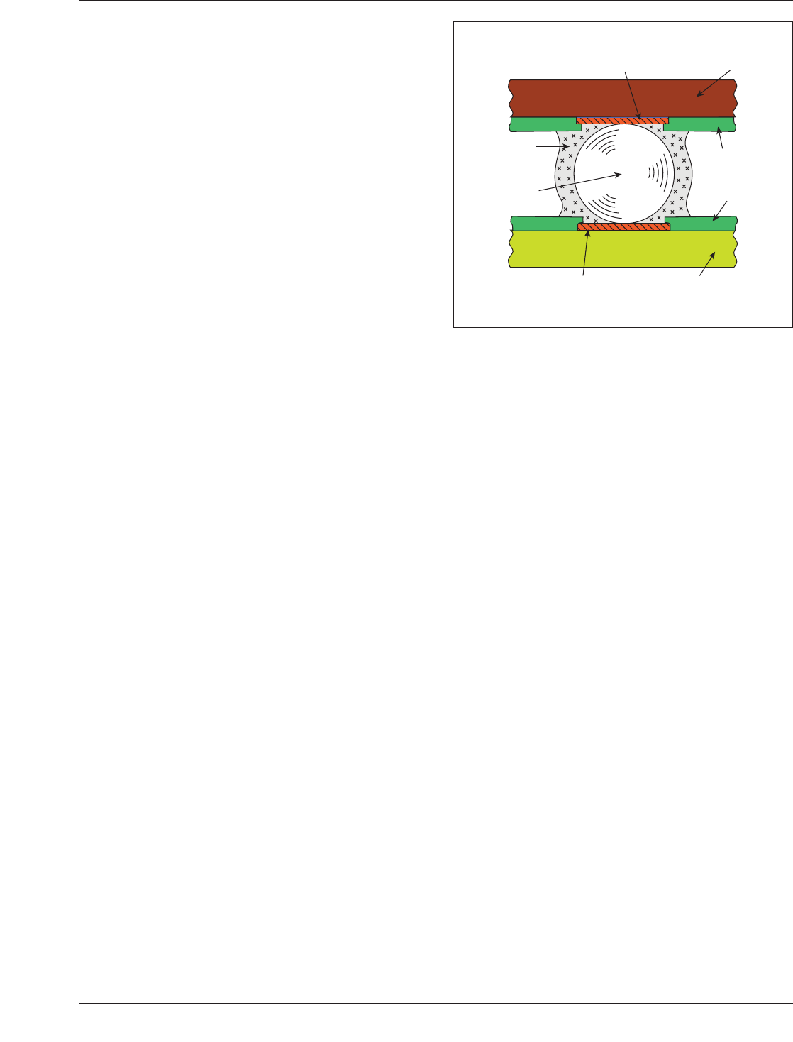
In an effort to develop new attachment methods, a patent
was filed in the late 1990’s that uses a polymer-coated ball
as the interconnection media. The metallic sphere is con-
ductive and may be made of copper, silver, gold, solder,
etc. and then coated with the conductive polymer. The
method of coating is left up to the ball producer and may
be of different thickness as required for the application.
This novel interconnect method was developed in order to
address the different CTE of a ceramic interposer and the
organic board. Several technical papers have been pub-
lished on the system that heats the interfaces and how the
conductive polymer joins the land on the interposer and the
board. Temperature cycling data was obtained from both
conventional and polymer core balls tested on ceramic
packages mounted on an FR-4 board. An electrical simula-
tion was also performed to compare the polymer-core ball
with a conventional solder ball. Figure 4-6 shows the con-
cept of the process.
Laminate and polyimide film-based BGAs are very differ-
ent, however. The laminate based package is essentially
made of circuit board material with a high temperature (T
g
)
rating. A high T
g
rated resin system adopted by several
companies for BGA package applications is bismaleimide
triazine (BT). Reinforced polyimides and polyimide films
have an even higher temperature rating and are also in
wide use for both BGAs and FBGAs.
4.4.1 Solder Ball Alloy Solder ball composition is
defined by the overall PCA technology, e.g., tin/lead or
lead-free, and the package type, e.g., ceramic or laminate
substrate. The alloy composition selected for ball contacts
on reinforced laminate and polyimide film based BGA
packages can vary a great deal. Many are furnished with a
tin/lead eutectic solder having a melting (liquidus) point of
183°C (or 179°C for eutectic solder with 2% silver). The
ball contacts are commonly applied to the package sub-
strate using only flux and a reflow soldering temperature of
215-220°C to complete the joining process.
4.4.1.1 Tin/Lead Technology Alloys Although not in
wide use for most commercial applications, tin/lead alloys
can be adapted for both solder ball and solder joining mate-
rials. One common alloy composition is the Sn63Pb37
eutectic, with a liquidus temperature of 183°C. The eutec-
tic silver containing alloy composition, Sn62Pn36Ag2, has
a liquidus temperature of 179°C and is an acceptable alter-
native to eutectic Sn63Pb37. Ceramic BGAs, when used in
the tin/lead technology, often employ a high-lead alloy of
Sn10Pb90 composition to provide the required solder joint
reliability. This alloy does not melt during the tin/lead
reflow process, but when attached to the PCB with eutectic
Sn63Pb37, provides a reliable interconnect.
4.4.1.2 Lead-free Technology Alloys In compliance
with the RoHS directive (Restriction of the Use of Certain
Hazardous Substances in Electrical and Electronic Equip-
ment), companies manufacturing electrical and electronic
assemblies and electrical components must use Pb-free
(lead free) materials for both ball contacts and package to
substrate joining. Although a number of Pb-free alloy
compositions are available, a majority of manufacturers
have adopted tin as the primary element and include
silver or a combination of silver and copper to the tin
alloy. Typical Pb-Free alloy compositions include
Sn96.5Ag3.0Cu0.5 (SAC305), Sn95.5Ag3.8Cu0.7
(SAC387) or Sn95.5Ag4.0Cu0.5 (SAC405). These solders
have liquidus temperatures in the range of 217-227°C and
IPC-7095c-4-6
Figure 4-6 Polymer Coated Sphere Interconnection
Copper
Land
Solder
Mask
Package
Substrate
Interconnection
Substrate
Copper
Land
Polymer
Core
Solder
January 2013 IPC-7095C
23
Copyright IPC-Association Connecting Electronics Industries
Provided by IHS under license with IPC
Not for Resale
No reproduction or networking permitted without license from IHS
--`,,```,,,,````-`-`,,`,,`,`,,`---