IPC-7095C-2013.pdf - 第86页
6.7.4.4 Gels Gels are comprised of a lightly cross-linked silicone polymer filled with metal or ceramic particles that impart the thermal conductivity necessary for this TIM. Gels combine the beneficial properties of greas…

or blower. Heat transfer by forced convection can be as
much as ten times more effective than natural convection.
6.7.4 Thermal Interface Materials Attachment of heat
sinks to BGAs is the most common technique today in
cooling the silicon devices packaged within the BGAs.
These heat sinks require a thermal interface material to be
sandwiched between the heat sink and the BGA in order to
conduct the heat from the top of the package surface and
into the bottom of the heat sink surface.
When selecting a thermal interface material, keep in mind
the surface flatness of the BGA body and the heatsink.
Warpage of the BGA package during reflow and large tol-
erances on the heatsink contact surface can result in large
gaps that are difficult to fill reliably with some interface
materials. This in turn can cause poor thermal conductivity
and/or a weak heatsink attachment bond.
There are various types of thermal interface materials
(TIM). These are described below.
6.7.4.1 Adhesives Metal filled epoxies and silicone
adhesives were commonly used as TIMs initially. They
play a dual part of being a TIM as well as a mechanical
attachment method since when cured they become highly
cross-linked and attain high cohesive strength. Hence,
unlike the other TIMs, supplementary mechanical attach-
ment methods are not necessary when using adhesive. Dis-
advantages of adhesives include a thermal cure step being
necessary after the BGA is soldered on the board and the
potential for severe delamination at the interfaces that the
adhesive bonds to due to coefficient of thermal expansion
mismatches between the heat sink and the package.
Another subclass of adhesives are the Pressure Sensitive
Adhesives (PSAs), which do not require a cure to generate
the interfacial bond, but instead require a certain amount of
pressure, typically in the 20 to 30 psi range. Their use for
BGAs is therefore limited since this pressure, if not prop-
erly controlled, may adversely impact the BGA solder
joints.
6.7.4.2 Greases Thermal greases are metal filled poly-
mers that have the inherent advantage of being a viscous
liquid and conforming to the macroscopic and microscopic
irregularities in the surfaces of the heat sink and the BGA
component. They have excellent thermal performance and,
unlike adhesives, do not require a cure. A major disadvan-
tage of thermal greases is that they tend to migrate out
from between the heat sink and package interfaces over
time. This phenomenon is known as ‘‘pump-out,’’ and is
caused by the thermo-mechanical stresses exerted at the
interfaces during temperature cycling.
6.7.4.3 Phase Change Materials (PCM) Phase change
materials are in a solid state at room temperature but
become liquid at the higher temperatures at which they are
required to conduct heat away from the BGA surface.
Hence, they offer ease of handling and dispensing because
they typically are in a film form and do not need to be
cured. However, their thermal conduction properties are
inferior to greases, adhesives and the other TIM alterna-
tives so they are only suitable for use with low wattage
devices.
Table 6-11 Effects of Material Type on Conduction
Materials
Thermal Conductivity (K)
Watts/inch °C Watts/m °C Gram-calorie/cm °C • s
Still Air 0.0007 0.0276 0.000066
Epoxy 0.005 0.200 0.00047
Thermally Conductive Epoxy 0.02 0.787 0.0019
Aluminum Alloy 1100 5.63 222 0.530
Aluminum Alloy 3003 4.88 192 0.459
Aluminum Alloy 5052 3.52 139 0.331
Aluminum Alloy 6061 4.36 172 0.410
Aluminum Alloy 6063 4.88 192 0.459
Copper 4.93 194 0.464
Steel Low Carbon 1.19 46.9 0.112
Table 6-12 Emissivity Ratings for Certain Materials
Material and Finish Emissivity
Aluminum Sheet - Polished 0.040
Aluminum Sheet - Rough 0.055
Anodized Aluminum - any color 0.80
Brass - Commercial 0.040
Copper - Commercial 0.030
Copper - Machined 0.072
Steel - Rolled Sheet 0.55
Steel - Oxided 0.667
Nickel Plate - Dull Finish 0.11
Silver 0.022
Tin 0.043
Oil Paints - Any Color 0.92-0.96
Lacquer - Any Color 0.80-0.95
January 2013 IPC-7095C
71
Copyright IPC-Association Connecting Electronics Industries
Provided by IHS under license with IPC
Not for Resale
No reproduction or networking permitted without license from IHS
--`,,```,,,,````-`-`,,`,,`,`,,`---
6.7.4.4 Gels Gels are comprised of a lightly cross-linked
silicone polymer filled with metal or ceramic particles that
impart the thermal conductivity necessary for this TIM.
Gels combine the beneficial properties of greases and cured
adhesives, do not pump-out and do not require a post appli-
cation cure step. Their modulus is low enough to relieve
thermo-mechanical stresses and avoid interfacial delamina-
tions. They have high bulk thermal conductivities and have
been used in cooling BGA components containing high
wattage CPU devices.
6.7.4.5 Thermal Conductive Pressure Sensitive Tape
Thermal conductive pressure sensitive tape may occasion-
ally be used to impart the thermal conductivity necessary to
remove heat from the BGA. This thermal interface material
is becoming more widely used due to the ease of handling
and applying to the surfaces that are used for cooling BGA
components.
6.7.5 Heat Sink Attachment Methods for BGAs There
are quite a few techniques for attaching heat sinks to
BGAs. These are depicted in the following illustrations.
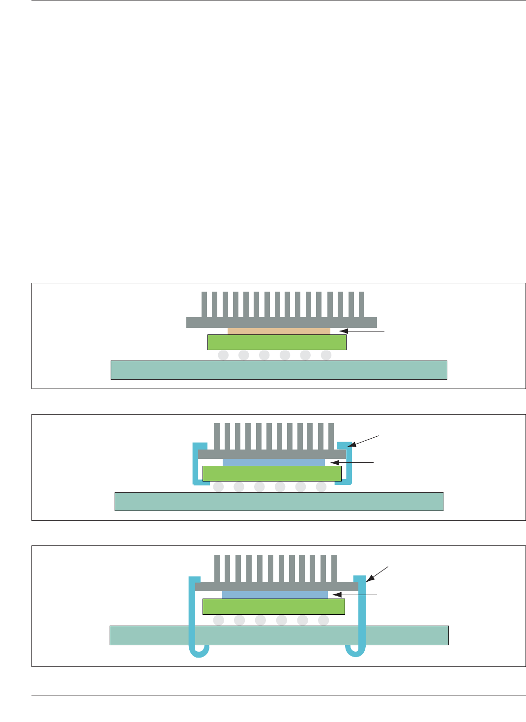
Figure 6-33 shows a heat sink attached to the top of a BGA
package with a thermally conductive adhesive. The adhe-
sive acts as both a thermal conduction medium as well as
a mechanical attachment medium. As mentioned above,
however, this technique requires a post solder thermal cure
step to cross-link the adhesive and harden it.
Figure 6-34 illustrates a heat sink attached to the top of a
BGA package with clips that hook on to a BGA substrate.
However, there is danger of damage to the solder joints
while attaching the clips. The thermal interface material in
this case is a grease, or PCM or gel, i.e., one that does not
provide a strong mechanical bond between the heat sink
and the top of the BGA package. This method has one
drawback. The weight of the heat sink is supported by the
package and, during mechanical shock and vibration, the
solder balls of the BGA have to bear the mechanical
stresses generated by the additional mass of the heat sink.
Figure 6-35 depicts the case of a heat sink attached to the
BGA with clips that hook into holes in the printed circuit
board. These holes do not have to be plated. Unlike the
IPC-7095c-6-33
Figure 6-33 Heat Sink Attached to a BGA with an Adhesive
BGA
Adhesive
Board
Heat Sink
IPC-7095c-6-34
Figure 6-34 Heat Sink Attached to a BGA with a Clip that Hooks onto the Component Substrate
Grease/
Gel/PCM
Board
Clip
BGA
Heat Sink
IPC-7095c-6-35
Figure 6-35 Heat Sink Attached to a BGA with a Clip that Hooks into a Through-Hole on the Printed Circuit Board
Board
Clip
Grease/
Gel/PCM
BGA
Heat Sink
IPC-7095C January 2013
72
Copyright IPC-Association Connecting Electronics Industries
Provided by IHS under license with IPC
Not for Resale
No reproduction or networking permitted without license from IHS
--`,,```,,,,````-`-`,,`,,`,`,,`---
previous case, the printed circuit board supports the weight
of the heat sink when the clips are actuated, but some stress
can still be transferred on to the BGA solder balls during
mechanical shock and vibration. In addition, the heat sink
may create a cantilevered load on the solder joint when the
assembly is in a vertical orientation. This load may lead to
premature solder joint failure.
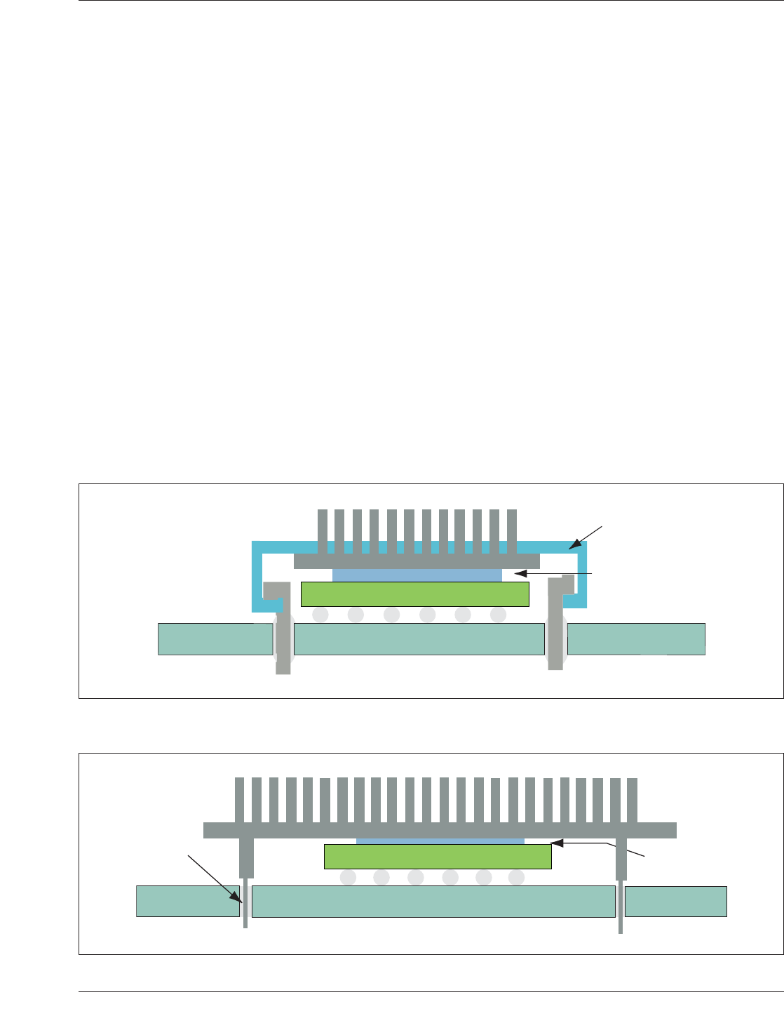
Figure 6-36 shows the case of a heat sink attached to a
BGA package with clips that hook on stakes that are wave
soldered into holes in the printed circuit board. This
method of attachment transfers even less stress on the BGA
solder balls during mechanical shock and vibration than the
previous case. However, the solder joints of the stakes will
bear most of this stress.
Figure 6-37 illustrates the attachment of the heat sink to a
BGA by directly soldering the heat sink into the board dur-
ing the wave soldering process step. The heat sink design
has four or more pins that insert into holes in the board
prior to the wave solder process. As opposed to the previ-
ous cases above, this method does not need any post
assembly processing to attach the heat sink.
The three methods in Figures 6-30, 6-31 and 6-32 have one
drawback not present in the first two. These methods
require holes in the printed circuit to be designed in. These
holes may reduce the trace routing real estate on all the
board layers. For highly dense board designs, this could
impact the final layer count of the board.
6.8 Documentation and Electronic Data Transfer The
documentation package for describing BGA components
usually consists of a master drawing, master pattern draw-
ing, copies of artwork (film or paper), mounting structure
assembly drawing, parts list, and schematic/logic diagram.
The documentation package may be provided in either hard
copy or electronic data. All information about documenta-
tion is also appropriate for electronic data transmission.
Since many CAD systems have their own native database,
everyone is promoting some form of unique format that has
a neutral concept, thus avoiding sending the native data-
base to the suppliers.
The lowest common denominator for years has been a
machine language. This may eventually be replaced by
such formats as the IPC-D-356, or IPC-2581. Archiving
electronic data should be in accordance with these docu-
ments. Delivery of computer generated data as a part of the
documentation package should meet the requirements
stated in those packages. With automated techniques, the
database shall detail all information that will be needed to
produce the printed board or mounting structure for the
bare die. This includes all notes, plating requirements,
IPC-7095c-6-36
Figure 6-36 Heat Sink Attached to a BGA with a Clip that Hooks onto a Stake Soldered in the Printed Circuit Board
Grease/
Gel/PCM
Board
BGA
Heat Sink
Clip
IPC-7095c-6-37
Figure 6-37 Heat Sink Attached to a BGA by Wave Soldering Its Pins in a Through-Hole in the Printed Circuit Board
Grease/
Gel/PCM
BGA
Heat
Sink
Pin
Board
January 2013 IPC-7095C
73
Copyright IPC-Association Connecting Electronics Industries
Provided by IHS under license with IPC
Not for Resale
No reproduction or networking permitted without license from IHS
--`,,```,,,,````-`-`,,`,,`,`,,`---