IPC-7095C-2013.pdf - 第105页
should be fabricated, or machines designed for breakaway tab removal should be purchased. These tools or machines should reduce or eliminate stress near BGA components during breakaway tab removal. 7.3 Inspection Techniq…
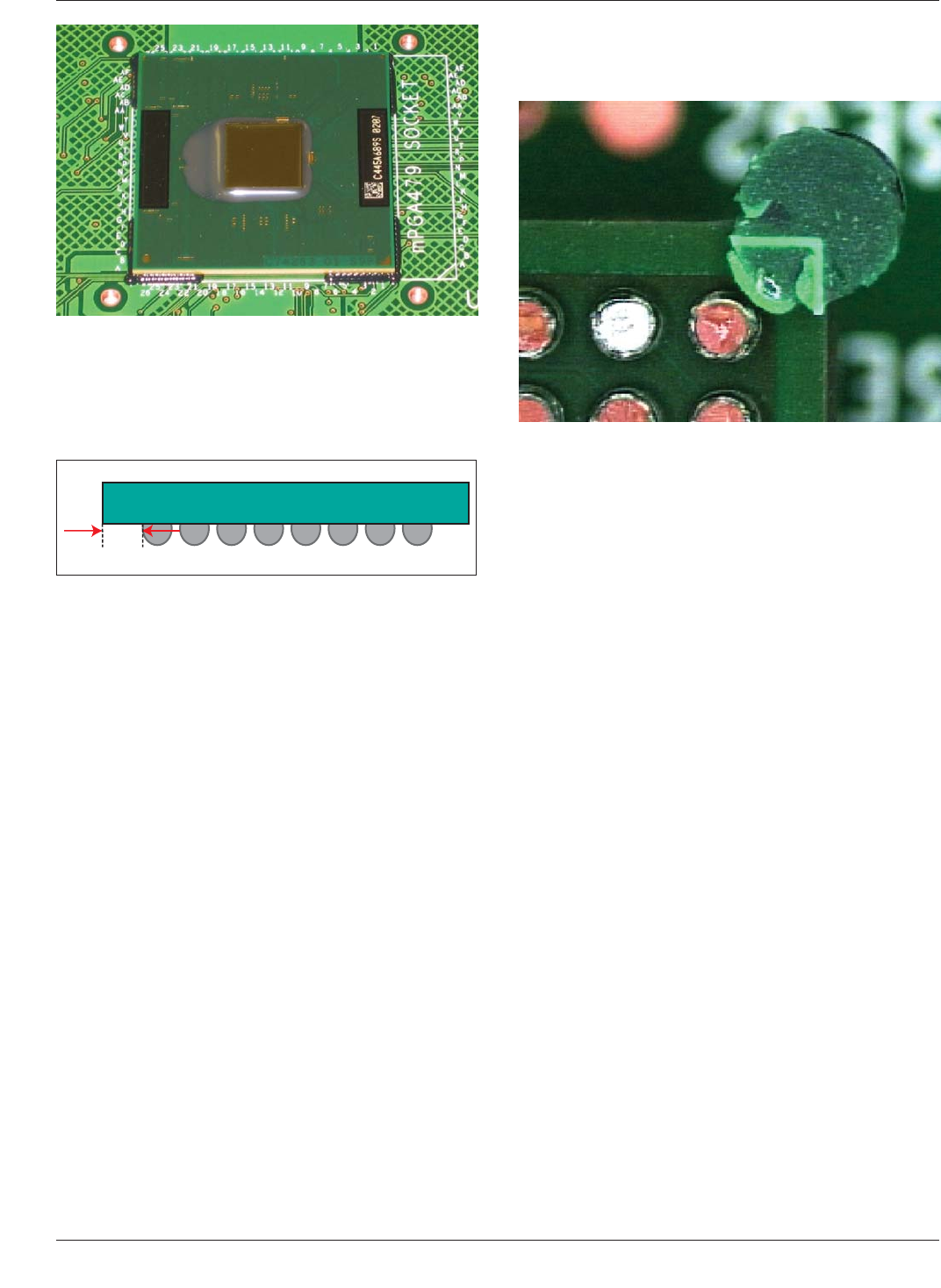
BGA package after reflow. Corner glue prior to reflow (pre-
reflow) requires that the BGA package have sufficient sub-
strate available outside of the edge of the last solder ball in
the outermost rows (see Figure 7-16).
The minimum width of available substrate where pre-flow
corner glue can be applied is approximately 0.7 mm. With
packages with less than this amount of substrate available,
this process is not controllable in HVM. Current trends are
that package substrate sizes are shrinking and the use of
pre-reflow applied corner glue is expected to drop off.
The effectiveness of corner glue post assembly and reflow
methods depends on the type of glue chosen and the total
surface area contacted at each corner. Dispensed amounts
vary from essentially single glue dots at each corner to ‘‘L’’
shaped brackets of glue that extend down the side of the
package by up to six solder balls on each side of the corner.
Studies show that the longer ‘‘L’’ shaped dispensed brack-
ets can significantly improve mechanical reliability (i.e.,
one study showed an improvement in shock performance
where the acceleration level caused the onset of mechani-
cal damage to occur, increasing from 180 G to 300 G.)
A good starting point for the amount of glue that should be
applied at each corner is that each leg of the ‘‘L’’ shaped
bracket should extend somewhere between 3 and 6 solder
balls deep. One pitfall of corner glue is using too little glue
in terms of the surface covered. Testing has shown that a
single dot of glue that covers no more than the width of
one solder ball down the side of the substrate does not sig-
nificantly increase the shock or bend performance of a
BGA. This is because typically the strength of the solder
mask to underlying FR-4 or the strength of the BGA sub-
strate is low and these constructions crack very easily if the
surface area of the corner glue is too low (see Figure 7-17).
Other guidelines are that the glue should wet on average at
least 50% up the vertical side of the substrate throughout
the entire dispense line and that the epoxy material should
be forced to flow to some degree underneath the BGA
package, even if the epoxy flows in deeply enough to con-
tact some of the solder balls.
Typical dispense equipment for post-reflow corner glue
includes a pneumatic source that supplies air to a syringe
and needle set up. This equipment is low cost and condu-
cive to being set up in manufacturing environments where
labor rates are fairly low compared to available capital.
Corner glues are epoxies similar to underfills. Typical cure
cycles include 5-60 minutes at 60-180°C. Some UV light
curable versions of these materials are also being intro-
duced.
7.2.3 Depaneling of Boards and Modules The method
for depanelization can be achieved using a number of
different techniques. These include simple scoring, a com-
bination of routing and scoring, and a combination of rout-
ing plus breakaway tabs (see IPC-2222).
Scoring is the machining of a shallow, precise V-groove
into the top and bottom surfaces of the laminate. As scor-
ing allows the removal of rails and individual parts from a
pallet, positional accuracy is critical. Routing defines the
final assembly periphery. The routing channels are pro-
duced using router bits of different diameters, leaving
breakaway tabs to hold the board in place during assembly.
Extreme care should be taken when breakaway tabs are
removed. Avoid bending the board, especially near BGA
components. Bending may cause BGA solder joints to
crack, typically starting with the corner balls. Custom tools
Figure 7-15 Corner Applied Adhesive
IPC-7095c-7-16
Figure 7-16 Critical Dimension for Application of Prere-
flow Corner Glue
Figure 7-17 Typical Corner Glue Failure Mode in Shock if
Glue Area is Too Low - Solder Mask Rips Off Board and
Does Not Protect the Solder Joints
IPC-7095C January 2013
90
Copyright IPC-Association Connecting Electronics Industries
Provided by IHS under license with IPC
Not for Resale
No reproduction or networking permitted without license from IHS
--`,,```,,,,````-`-`,,`,,`,`,,`---

should be fabricated, or machines designed for breakaway
tab removal should be purchased. These tools or machines
should reduce or eliminate stress near BGA components
during breakaway tab removal.
7.3 Inspection Techniques The following paragraphs
are inspection techniques that may be applied at different
times during the development of the BGA assembly pro-
cess or as an auditing mechanism during production. Table
7-4 provides some recommendations as to applicability of
the inspection method.
7.3.1 X-Ray Usage X-ray inspection is generally used
when there is a high proportion of hidden solder joints that
are not visually accessible, and when there are a significant
number of untestable solder joints. Examples of untestable
solder joints are redundant connections, and back-to-back
BGAs where the fanout vias are inaccessible and space
does not allow for additional test points. X-ray methods
can complement the test process chosen, and can provide
faster feedback to the manufacturing line. Depending on
the capability of the X-ray system being used, X-ray is
capable of detecting solder related defects such as bridging,
open solder joints, insufficient solder, and excessive solder
volume. Other defect types such as missing balls, misreg-
istration, and package popcorning can also be identified. In
addition to defect detection, X-ray can be used to provide
trend analysis for solder volume and solder joint shape.
X-ray is the only nondestructive method of finding voids in
BGA joints.
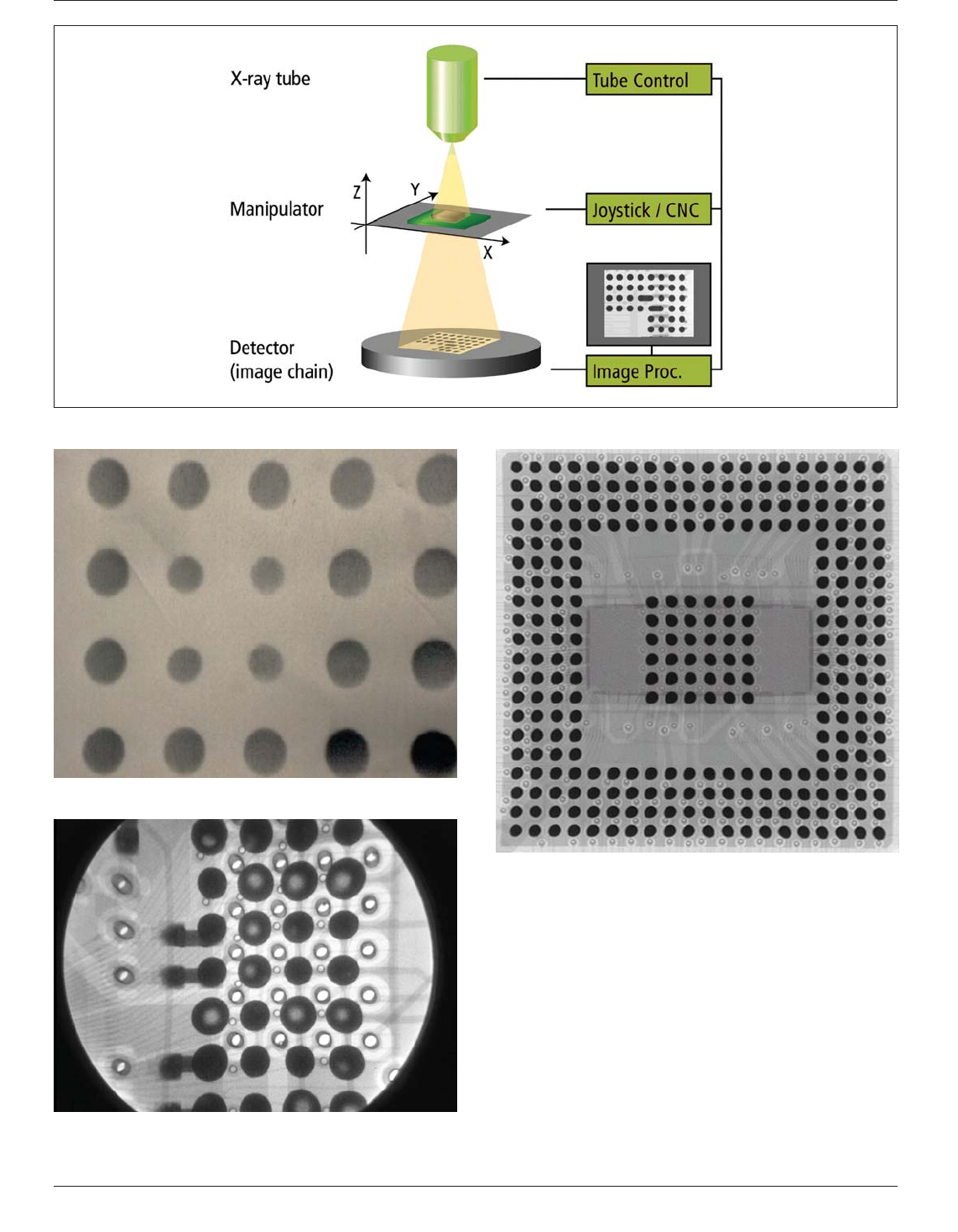
Figure 7-18 shows the principles of X-ray equipment being
used with the X-ray to be above the sample; some equip-
ments have the tube below or at an angle to the specimen.
The general characteristics provided in the figure apply to
most X-ray systems. X-ray inspection has become a gener-
ally accepted tool for solder joint evaluation and analysis,
and as a monitor for the reflow process. X-ray inspection
techniques can be employed most effectively through the
understanding of principles of X-ray image acquisition.
X-ray can be effective in confirming solder bond integrity
of BGAs and as a monitor for the reflow process. X-ray
inspection techniques can be employed most effectively
through the understanding of:
• Principles of X-ray image acquisition
• Analysis of the X-ray image (in the light of the reflow
process)
Use of X-ray requires some caution regarding overexpo-
sure on vulnerable materials or components. Figures 7-19
and 7-20 show the characteristics of X-ray images for both
voids at the interface, or missing solder balls in the BGA
attachment.
7.3.2 X-Ray Image Acquisition
7.3.2.1 Film Based X-Ray Inspection
Film based X-ray
inspection systems employ an industrial X-ray cabinet and
X-ray film packets to record the X-ray image on film. The
film can then be viewed on video film viewers for high
magnification examination of details. The process is slow
but can yield X-ray images of great detail and tonal accu-
racy.
7.3.2.2 Real Time X-Ray Systems Real Time X-ray
inspection systems utilize an X-ray source and a detector
system which converts the invisible X-ray image into a
video display signal. These systems provide immediate
imaging results of samples. The images produced from
these systems should not be distorted or include false arti-
facts induced by the X-ray system itself. Figure 7-21 illus-
trates a comparable level of image quality that should be
expected from a manual X-ray inspection system. Figure
7-22 illustrates examples of pin-cushion distortion and
voltage blooming. Real time systems are available in a
broad range of sizes from small desktop systems to large
Table 7-4 Inspection Usage Application Recommendations
Method
Process
Development
In-Line
Production
Failure
Analysis
Process
Auditing
NPI or Low
Volume
Production
Optical Inspection Excellent Good Excellent Good Good
Manual X-ray Excellent Good Excellent Good Excellent
Automated Transmission
X-Ray
Excellent Excellent Good Good Good
Automated Cross Section
X-Ray
Excellent Excellent Excellent Good Good
Scanning Acoustic Microscopy Excellent Fair Good Good Fair
Stand Off Measurement Fair Fair Good Good Fair
Automatic Optical Inspection
Solder paste
volume
Part
identification,
solder paste
volume
Not Applicable
Part
identification,
solder paste
volume
Part
identification,
solder paste
volume
Destructive Analysis Good Poor Excellent Fair Fair
January 2013 IPC-7095C
91
Copyright IPC-Association Connecting Electronics Industries
Provided by IHS under license with IPC
Not for Resale
No reproduction or networking permitted without license from IHS
--`,,```,,,,````-`-`,,`,,`,`,,`---
console floor models. They are also available with a broad
range of X-ray source voltages. There is not a specific
voltage needed to inspect BGAs. The voltage required will,
in part, depend on the sensitivity of the particular X-ray
system employed, as well as the structure and characteris-
tics of the BGA under inspection. BGAs with copper heat
sinks for example, will require higher penetrating voltage
settings than PBGAs or CBGAs. BGAs with aluminum
heat sinks, on the other hand, do not require the higher
voltages since aluminum is a less dense material and is
therefore much more transparent to X-rays than copper.
7.3.3 Definition and Discussion of X-Ray System Termi-
nology
X-ray inspection systems are available in both
IPC-7095c-7-18
Figure 7-18 Fundamentals of X-Ray Technology
Figure 7-19 X-Ray Example of Missing Solder Balls
Figure 7-20 X-ray Example of Voiding in Solder Ball Con-
tacts
Figure 7-21 Manual X-Ray System Image Quality
IPC-7095C January 2013
92
Copyright IPC-Association Connecting Electronics Industries
Provided by IHS under license with IPC
Not for Resale
No reproduction or networking permitted without license from IHS
--`,,```,,,,````-`-`,,`,,`,`,,`---