IPC-7095C-2013.pdf - 第107页
manual (MXI) and automated (AXI) configurations. MXI systems can have varying degrees of automation which can include automatic BGA analysis, automatic image process- ing functions, automated manipulation and board handli…
console floor models. They are also available with a broad
range of X-ray source voltages. There is not a specific
voltage needed to inspect BGAs. The voltage required will,
in part, depend on the sensitivity of the particular X-ray
system employed, as well as the structure and characteris-
tics of the BGA under inspection. BGAs with copper heat
sinks for example, will require higher penetrating voltage
settings than PBGAs or CBGAs. BGAs with aluminum
heat sinks, on the other hand, do not require the higher
voltages since aluminum is a less dense material and is
therefore much more transparent to X-rays than copper.
7.3.3 Definition and Discussion of X-Ray System Termi-
nology
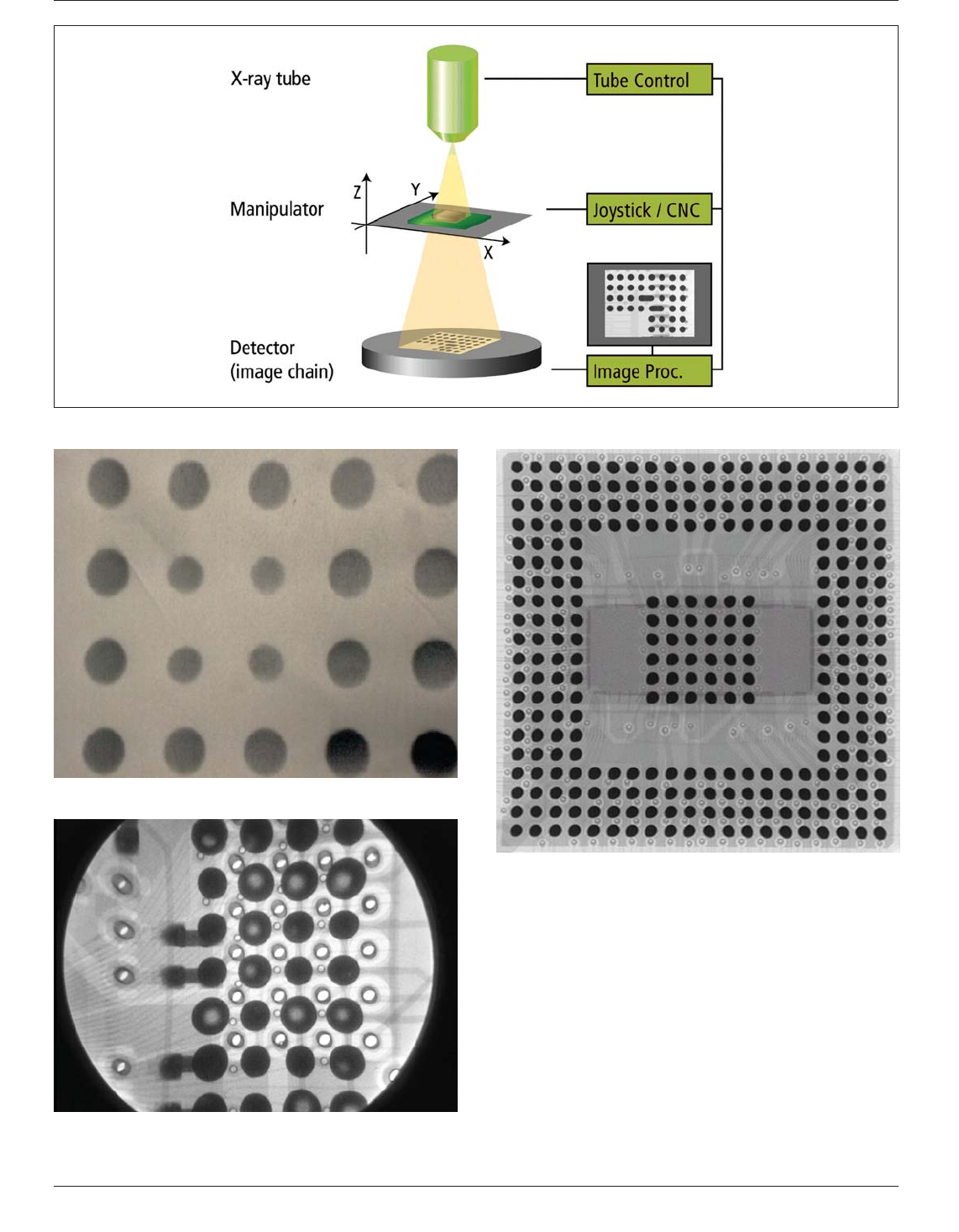
X-ray inspection systems are available in both
IPC-7095c-7-18
Figure 7-18 Fundamentals of X-Ray Technology
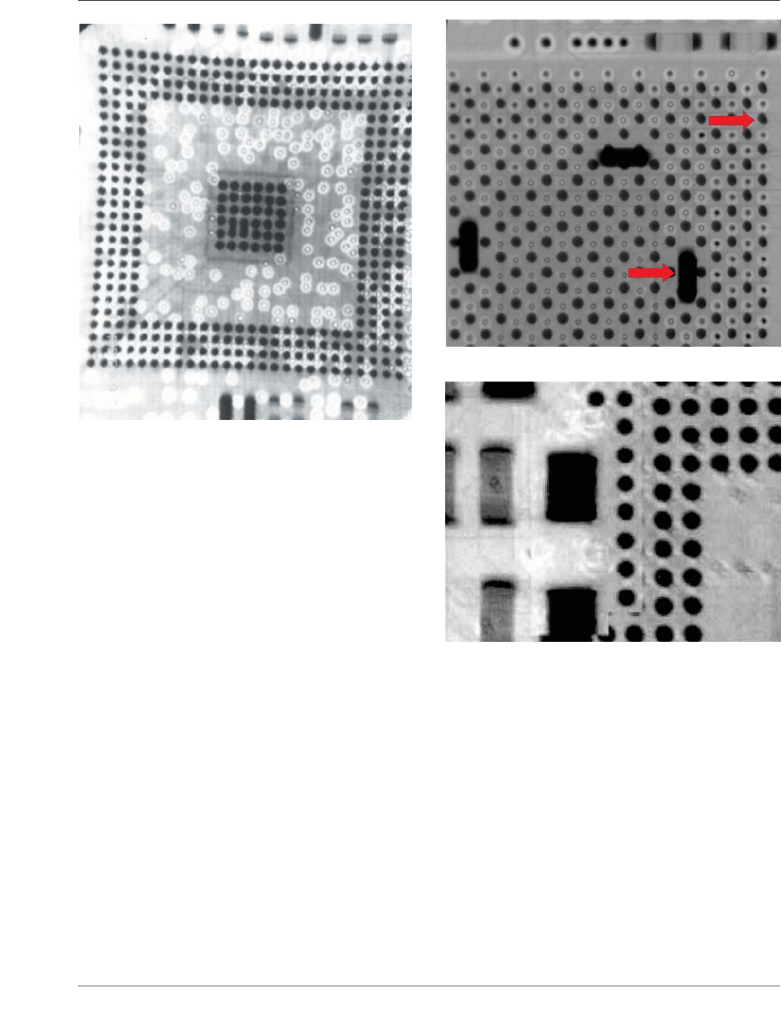
Figure 7-19 X-Ray Example of Missing Solder Balls
Figure 7-20 X-ray Example of Voiding in Solder Ball Con-
tacts
Figure 7-21 Manual X-Ray System Image Quality
IPC-7095C January 2013
92
Copyright IPC-Association Connecting Electronics Industries
Provided by IHS under license with IPC
Not for Resale
No reproduction or networking permitted without license from IHS
--`,,```,,,,````-`-`,,`,,`,`,,`---
manual (MXI) and automated (AXI) configurations. MXI
systems can have varying degrees of automation which can
include automatic BGA analysis, automatic image process-
ing functions, automated manipulation and board handling.
Another feature available with transmission target X-ray
systems is high magnification using an oblique view (see
7.3.3.2).
What generally distinguishes AXI systems from MXI sys-
tems is that AXI systems are in-line capable and do not
require an operator to make pass/fail decisions. MXI equip-
ment is almost exclusively transmission X-ray technology,
whereas AXI equipment can be transmission, cross-section
and combination.
AXI equipment is generally available in three forms:
• Transmission AX- - commonly referred to as 2-D X-ray
• Cross-Section AX- - commonly referred to as 3-D X-ray
• Combination 2-D/3-D AXI
The following definitions for Transmission, Cross-section
and Combo Automatic X-ray Inspection apply:
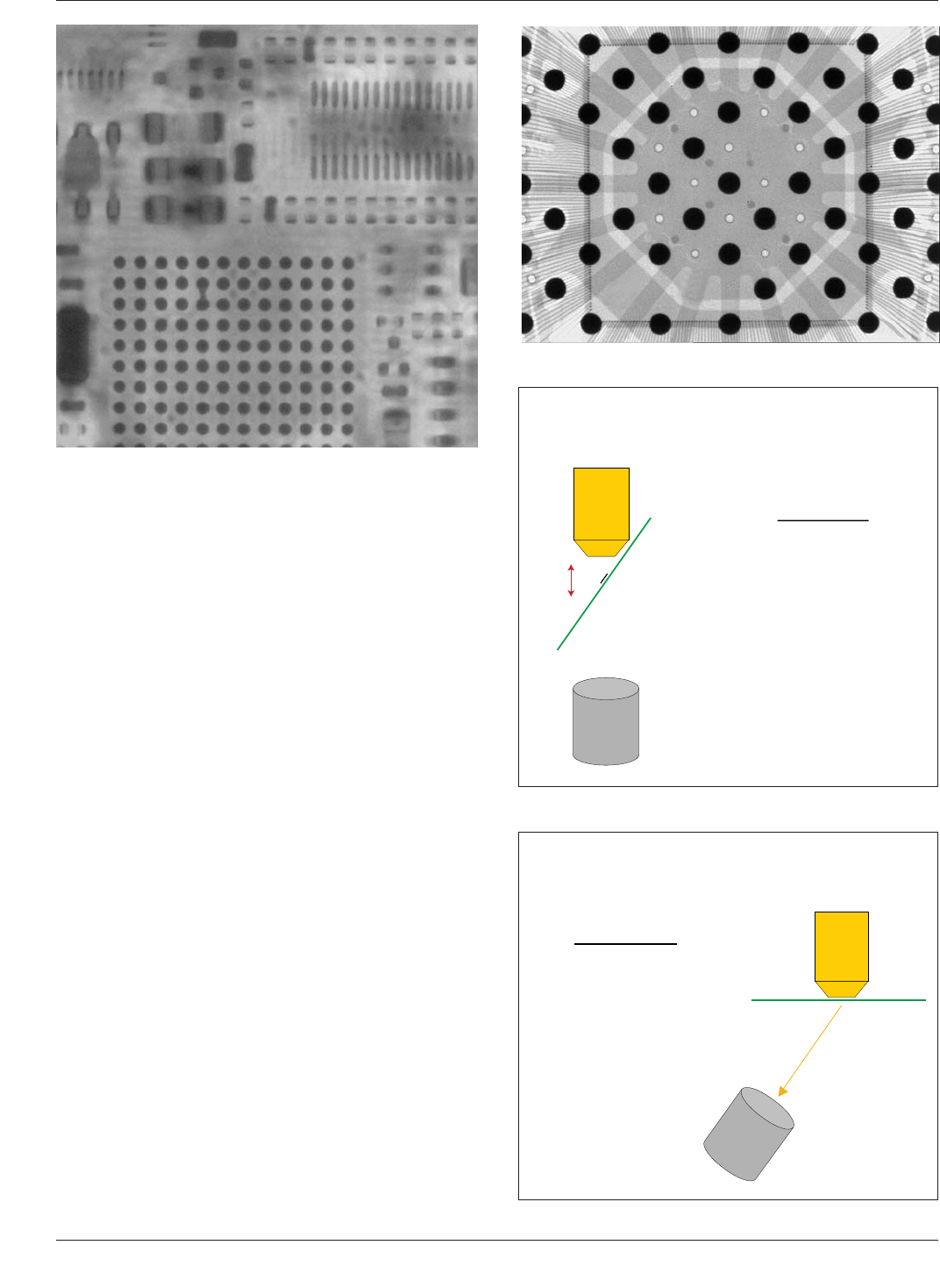
Transmission X-ray automatically generates images of all
features of the sample between the X-ray source and the
detector. Figures 7-23 through 7-25 show examples of
transmission, tomosynthesis, and laminographic X-ray
images.
Cross-section AXI automatically generates images of one
slice of the board at a time. Laminography and tomosyn-
thesis are the most common forms of cross-section AXI.
Combo AXI equipment uses a combination of transmission
and cross-section techniques concurrently during the
inspection of a PCB. Combo systems automatically apply
each technique where it is best suited and allow users the
ability to prefer one technique to another if desired. On
assemblies with components on both sides (Type 2), some
subset of the solder joints will be inaccessible to the stan-
dard transmission X-ray technique due to overlap, unless
an oblique viewing method is utilized.
The cross-section technique on the other hand, will have
greater test access where oblique viewing is not utilized.
Since the transmission X-ray technique captures informa-
tion from the entire solder volume, and the cross-section
technique captures specific slice information, these
techniques have both unique and common capabilities to
detect some types of solder defects. All of transmission,
cross-section and combo X-ray techniques are capable of
Figure 7-22 Example of X-Ray Pin Cushion Distortion and
Voltage Blooming
Figure 7-23 Transmission image (2D)
Figure 7-24 Tomosynthesis image (3D)
January 2013 IPC-7095C
93
Copyright IPC-Association Connecting Electronics Industries
Provided by IHS under license with IPC
Not for Resale
No reproduction or networking permitted without license from IHS
--`,,```,,,,````-`-`,,`,,`,`,,`---
detecting PCB assembly defects that cause changes in the
solder joint profile. These types of assembly defects
include but are not limited to: solder shorts, solder opens,
insufficient solder joints, missing devices, skewed devices,
and solder voids.
7.3.3.1 Transmission X-Ray Technology In transmis-
sion X-ray, the X-ray source and detector can be fixed or
movable in a variety of motions for variations in magnifi-
cation and angle of view. Generally, all features in the ver-
tical ‘‘line of sight’’ are viewed concurrently without dis-
tinguishing depth.
Differences in material thickness or density will result in
different transmitted X-ray attenuation at the detector
resulting in brighter or darker intensities within the image
display. For a single material type, such as eutectic solder,
the attenuation of the X-ray photons received at the detec-
tor is proportional to the material thickness. A gray scale
image is created which can be interpreted to determine
whether or not solder joints are acceptable. Figure 7-26
shows a transmission inspection illustration.
7.3.3.2 Oblique Viewing Inspections with Transmission
X-Ray Technology
There are two basic methods of
oblique viewing of objects with transmission X-ray sys-
tems. One method consists of tilting the sample in order to
get the oblique angle as illustrated in Figure 7-27. Although
this method enables the oblique view, the technique may
not allow for the highest achievable level of magnification
to be realized.
Another method of oblique viewing utilizes a wide angle
transmission X-ray source as illustrated in Figure 7-28. In
this method, the detector rotates around the center axis of
Figure 7-25 Laminographic Cross-Section Image (3D)
Figure 7-26 Transmission Example
IPC-7095c-7-27
Figure 7-27 Oblique Viewing Board Tilt
Oblique Viewing with Board Tilt
Detector
Board with
FBGA
Tilted View
High magnification is
required, but loss of
magnification occurs
through object tilt.
(Due to longer source
to
object distance.)
IPC-7095c-7-28
Figure 7-28 Oblique Viewing Detector Tilt
Oblique View without
Compromising Available Magnification
Detector
Board with
FBGA
Oblique View
High magnification is
required and maintained by
rotating the detector
through the cone of
radiation while keeping it
perpendicular to the center
of the x-ray source.
(Due to shorter source to
object distance.)
IPC-7095C January 2013
94
Copyright IPC-Association Connecting Electronics Industries
Provided by IHS under license with IPC
Not for Resale
No reproduction or networking permitted without license from IHS
--`,,```,,,,````-`-`,,`,,`,`,,`---