IPC-7095C-2013.pdf - 第106页
console floor models. They are also available with a broad range of X-ray source voltages. There is not a specific voltage needed to inspect BGAs. The voltage required will, in part, depend on the sensitivity of the partic…

should be fabricated, or machines designed for breakaway
tab removal should be purchased. These tools or machines
should reduce or eliminate stress near BGA components
during breakaway tab removal.
7.3 Inspection Techniques The following paragraphs
are inspection techniques that may be applied at different
times during the development of the BGA assembly pro-
cess or as an auditing mechanism during production. Table
7-4 provides some recommendations as to applicability of
the inspection method.
7.3.1 X-Ray Usage X-ray inspection is generally used
when there is a high proportion of hidden solder joints that
are not visually accessible, and when there are a significant
number of untestable solder joints. Examples of untestable
solder joints are redundant connections, and back-to-back
BGAs where the fanout vias are inaccessible and space
does not allow for additional test points. X-ray methods
can complement the test process chosen, and can provide
faster feedback to the manufacturing line. Depending on
the capability of the X-ray system being used, X-ray is
capable of detecting solder related defects such as bridging,
open solder joints, insufficient solder, and excessive solder
volume. Other defect types such as missing balls, misreg-
istration, and package popcorning can also be identified. In
addition to defect detection, X-ray can be used to provide
trend analysis for solder volume and solder joint shape.
X-ray is the only nondestructive method of finding voids in
BGA joints.
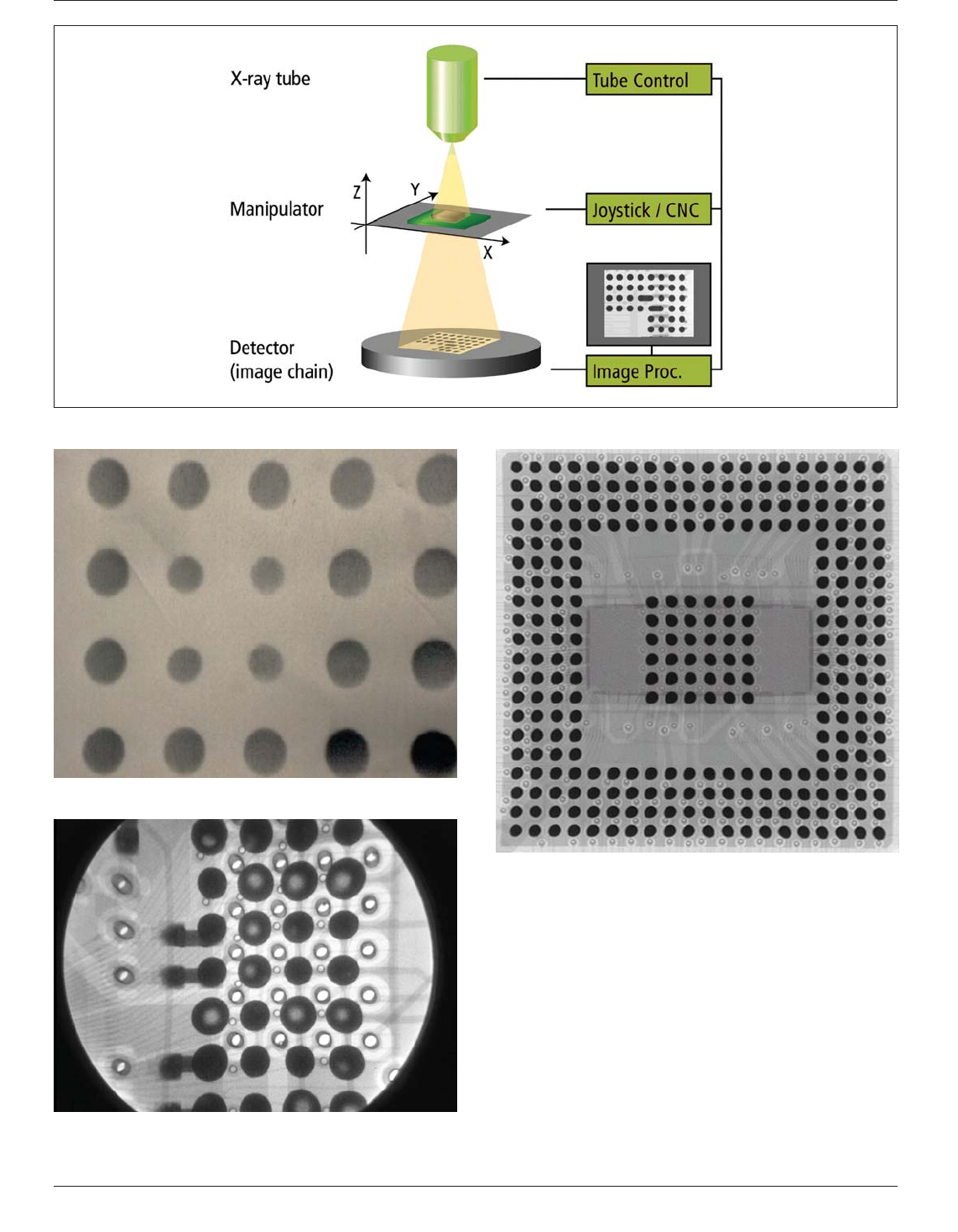
Figure 7-18 shows the principles of X-ray equipment being
used with the X-ray to be above the sample; some equip-
ments have the tube below or at an angle to the specimen.
The general characteristics provided in the figure apply to
most X-ray systems. X-ray inspection has become a gener-
ally accepted tool for solder joint evaluation and analysis,
and as a monitor for the reflow process. X-ray inspection
techniques can be employed most effectively through the
understanding of principles of X-ray image acquisition.
X-ray can be effective in confirming solder bond integrity
of BGAs and as a monitor for the reflow process. X-ray
inspection techniques can be employed most effectively
through the understanding of:
• Principles of X-ray image acquisition
• Analysis of the X-ray image (in the light of the reflow
process)
Use of X-ray requires some caution regarding overexpo-
sure on vulnerable materials or components. Figures 7-19
and 7-20 show the characteristics of X-ray images for both
voids at the interface, or missing solder balls in the BGA
attachment.
7.3.2 X-Ray Image Acquisition
7.3.2.1 Film Based X-Ray Inspection
Film based X-ray
inspection systems employ an industrial X-ray cabinet and
X-ray film packets to record the X-ray image on film. The
film can then be viewed on video film viewers for high
magnification examination of details. The process is slow
but can yield X-ray images of great detail and tonal accu-
racy.
7.3.2.2 Real Time X-Ray Systems Real Time X-ray
inspection systems utilize an X-ray source and a detector
system which converts the invisible X-ray image into a
video display signal. These systems provide immediate
imaging results of samples. The images produced from
these systems should not be distorted or include false arti-
facts induced by the X-ray system itself. Figure 7-21 illus-
trates a comparable level of image quality that should be
expected from a manual X-ray inspection system. Figure
7-22 illustrates examples of pin-cushion distortion and
voltage blooming. Real time systems are available in a
broad range of sizes from small desktop systems to large
Table 7-4 Inspection Usage Application Recommendations
Method
Process
Development
In-Line
Production
Failure
Analysis
Process
Auditing
NPI or Low
Volume
Production
Optical Inspection Excellent Good Excellent Good Good
Manual X-ray Excellent Good Excellent Good Excellent
Automated Transmission
X-Ray
Excellent Excellent Good Good Good
Automated Cross Section
X-Ray
Excellent Excellent Excellent Good Good
Scanning Acoustic Microscopy Excellent Fair Good Good Fair
Stand Off Measurement Fair Fair Good Good Fair
Automatic Optical Inspection
Solder paste
volume
Part
identification,
solder paste
volume
Not Applicable
Part
identification,
solder paste
volume
Part
identification,
solder paste
volume
Destructive Analysis Good Poor Excellent Fair Fair
January 2013 IPC-7095C
91
Copyright IPC-Association Connecting Electronics Industries
Provided by IHS under license with IPC
Not for Resale
No reproduction or networking permitted without license from IHS
--`,,```,,,,````-`-`,,`,,`,`,,`---
console floor models. They are also available with a broad
range of X-ray source voltages. There is not a specific
voltage needed to inspect BGAs. The voltage required will,
in part, depend on the sensitivity of the particular X-ray
system employed, as well as the structure and characteris-
tics of the BGA under inspection. BGAs with copper heat
sinks for example, will require higher penetrating voltage
settings than PBGAs or CBGAs. BGAs with aluminum
heat sinks, on the other hand, do not require the higher
voltages since aluminum is a less dense material and is
therefore much more transparent to X-rays than copper.
7.3.3 Definition and Discussion of X-Ray System Termi-
nology
X-ray inspection systems are available in both
IPC-7095c-7-18
Figure 7-18 Fundamentals of X-Ray Technology
Figure 7-19 X-Ray Example of Missing Solder Balls
Figure 7-20 X-ray Example of Voiding in Solder Ball Con-
tacts
Figure 7-21 Manual X-Ray System Image Quality
IPC-7095C January 2013
92
Copyright IPC-Association Connecting Electronics Industries
Provided by IHS under license with IPC
Not for Resale
No reproduction or networking permitted without license from IHS
--`,,```,,,,````-`-`,,`,,`,`,,`---
manual (MXI) and automated (AXI) configurations. MXI
systems can have varying degrees of automation which can
include automatic BGA analysis, automatic image process-
ing functions, automated manipulation and board handling.
Another feature available with transmission target X-ray
systems is high magnification using an oblique view (see
7.3.3.2).
What generally distinguishes AXI systems from MXI sys-
tems is that AXI systems are in-line capable and do not
require an operator to make pass/fail decisions. MXI equip-
ment is almost exclusively transmission X-ray technology,
whereas AXI equipment can be transmission, cross-section
and combination.
AXI equipment is generally available in three forms:
• Transmission AX- - commonly referred to as 2-D X-ray
• Cross-Section AX- - commonly referred to as 3-D X-ray
• Combination 2-D/3-D AXI
The following definitions for Transmission, Cross-section
and Combo Automatic X-ray Inspection apply:
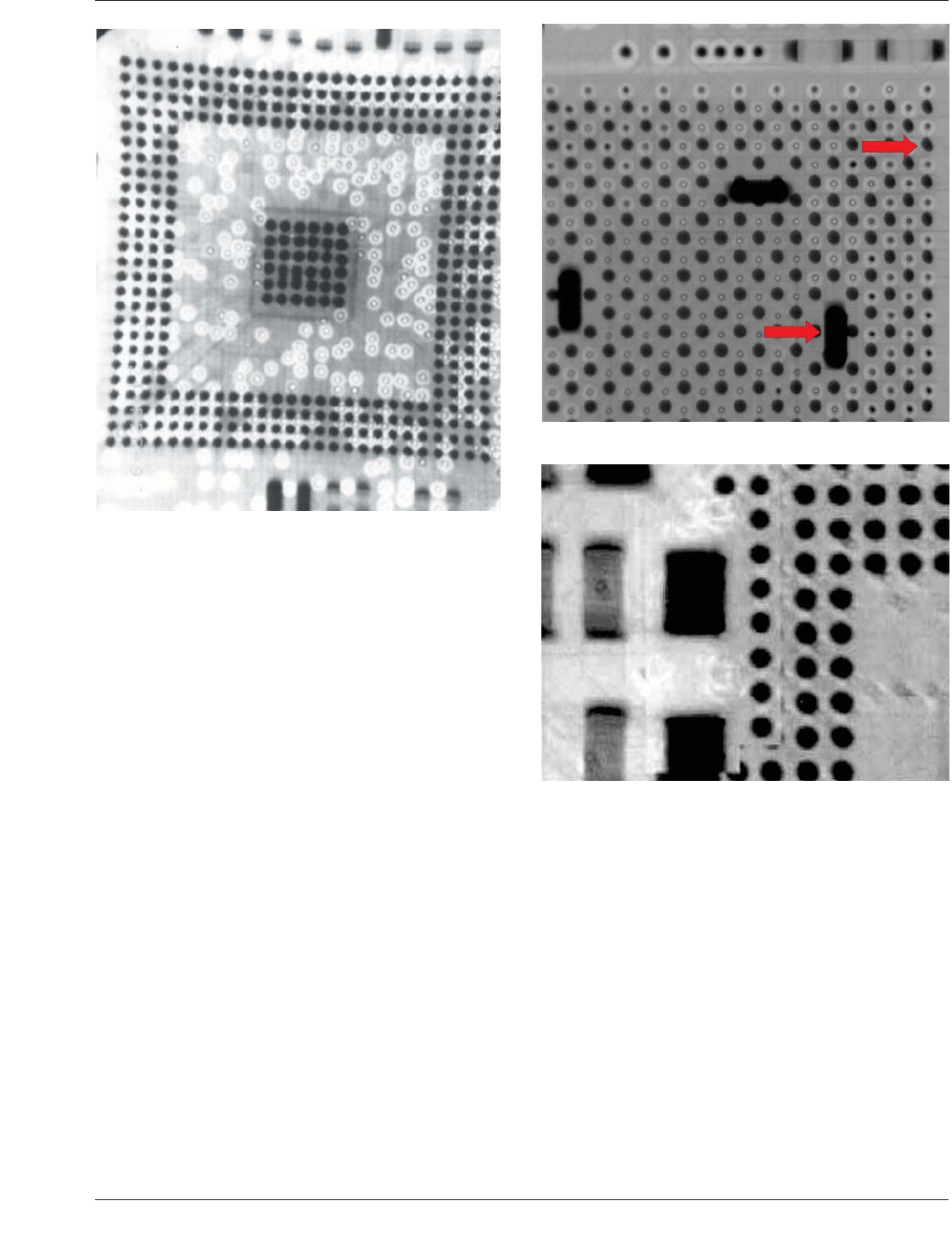
Transmission X-ray automatically generates images of all
features of the sample between the X-ray source and the
detector. Figures 7-23 through 7-25 show examples of
transmission, tomosynthesis, and laminographic X-ray
images.
Cross-section AXI automatically generates images of one
slice of the board at a time. Laminography and tomosyn-
thesis are the most common forms of cross-section AXI.
Combo AXI equipment uses a combination of transmission
and cross-section techniques concurrently during the
inspection of a PCB. Combo systems automatically apply
each technique where it is best suited and allow users the
ability to prefer one technique to another if desired. On
assemblies with components on both sides (Type 2), some
subset of the solder joints will be inaccessible to the stan-
dard transmission X-ray technique due to overlap, unless
an oblique viewing method is utilized.
The cross-section technique on the other hand, will have
greater test access where oblique viewing is not utilized.
Since the transmission X-ray technique captures informa-
tion from the entire solder volume, and the cross-section
technique captures specific slice information, these
techniques have both unique and common capabilities to
detect some types of solder defects. All of transmission,
cross-section and combo X-ray techniques are capable of
Figure 7-22 Example of X-Ray Pin Cushion Distortion and
Voltage Blooming
Figure 7-23 Transmission image (2D)
Figure 7-24 Tomosynthesis image (3D)
January 2013 IPC-7095C
93
Copyright IPC-Association Connecting Electronics Industries
Provided by IHS under license with IPC
Not for Resale
No reproduction or networking permitted without license from IHS
--`,,```,,,,````-`-`,,`,,`,`,,`---