TR7500E_Manual_en_v28.pdf - 第106页
C h a p t e r 2 M a nu a l B a r i n t r o d u ce T R 7500 U S E R M A N U AL 99 l U s i ng t h e f u n c t i o n t o i m p o r t a B O M f il e f o r a c o m p l e ti ng p r o j ec t i s t o s e t t h e c o mp o n e n t…
Chapter 2 Manual Bar introduce
TR7500 USER MANUAL
98
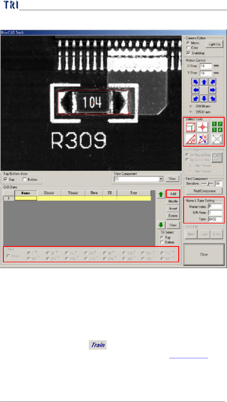
following.
Step2. Move selecting tools to the objective component center and the component has
to be on board 1.
Step3. Input data at [Name&Type Setting] field
Step4. Check [Apply] and select an angle.
Step5. Press [CAD Data/Add] to create the component data.
Step6. Add the other components on board 1.
Step7. Press [Close] to exit.
Step8. Press [Program/Train] or [ ] to enter the train dialog.
Step9. Use [Merge] button to merge the component library. See Chapter 4 6.8. for
more information about “Merge”.
Step10. Press [Utilities/Capture FOV Images] to get the FOV images again.
4.8. BOM Check
Step3
Step4
Step5
Step7
Step2
Chapter 2 Manual Bar introduce
TR7500 USER MANUAL
99
l Using the function to import a BOM file for a completing project is to set the
component that is not listed on BOM file as “Untest”. The format of BOM file is
in Chapter 3 1.1. (3).
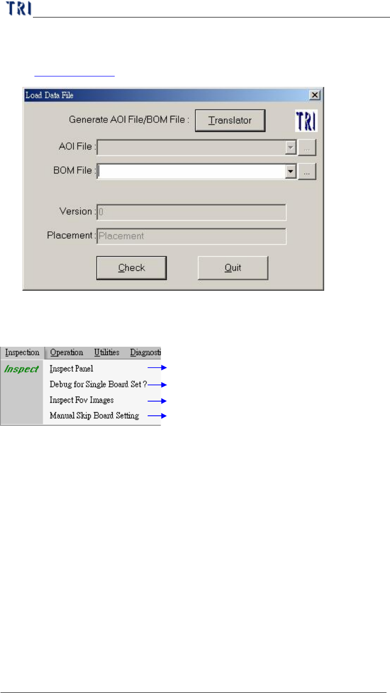
5. Inspection
Start to inspect
Only show single board result
Inspect saved FOV images
Specify single to test or not
5.1. Inspect Panel
l Start to inspect the PCB with standard procedure.
5.2. Debug for Single Board Set
l Start to inspect, but it shows only the result of one set.
5.3. Inspect FOV Images
l Inspect the FOV images that are saved in hard disk.
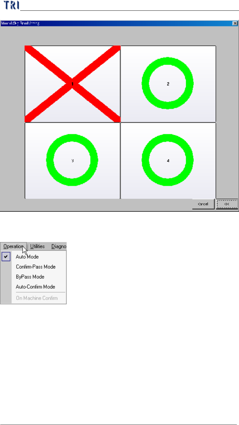
5.4. Manual Skip Board Setting
l You can use this function to specify every single board to be tested or not.
l As the image below, click on the board directly; the green [O] means that the
single have to be inspected and the red [X] means that the single board doesn’t
have to be inspected. Then press [OK] to finish sitting.
Chapter 2 Manual Bar introduce
TR7500 USER MANUAL
100
6. Operation
6.1. Auto Mode
l After inspecting system output the result and start to inspect the next PCB
directly.
6.2. Confirm-Pass Mode
l After inspecting system output the result. The next PCB will be inspected until
operator confirm.
6.3. ByPass Mode
l The output is always “Pass”