TR7500E_Manual_en_v28.pdf - 第90页
C h a p t e r 2 M a nu a l B a r i n t r o d u ce T R 7500 U S E R M A N U AL 83 l C r o ss l i ne n It ’ s a t o o l t o d e f i n e t h e c o o r d i n a t e s o f c o m po n e n t s . T h e s y s t e m wil l s e t t h…
Chapter 2 Manual Bar introduce
TR7500 USER MANUAL
82
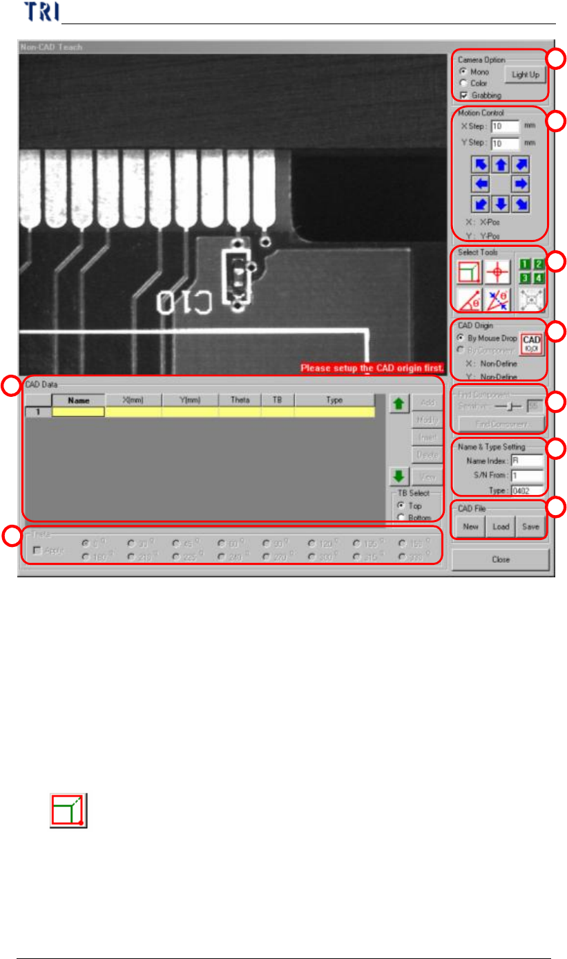
(1) Camera Option - Check [Grabbing] to capture real time image. You can select
[Mono] to see gray image or [Color] to see color image. Press [Light Up] to set
the lighting.
(2) Motion Control - You can use the function to move camera to specific
direction and distance or right click mouse on the image area to move the camera
to specific position.
(3) Tool - You can use these tools to create CAD file.
l
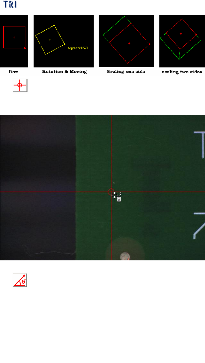
Box tool
n It’s a tool to define the coordinates of components. Press the button then a
box tool present. The box can be moved, rotated and resized by mouse. The
system will set the center of box as the component center.
1
2
3
4
5
6
7
8
9
Chapter 2 Manual Bar introduce
TR7500 USER MANUAL
83
l
Cross line
n It’s a tool to define the coordinates of components. The system will set the
cross center as the component center.
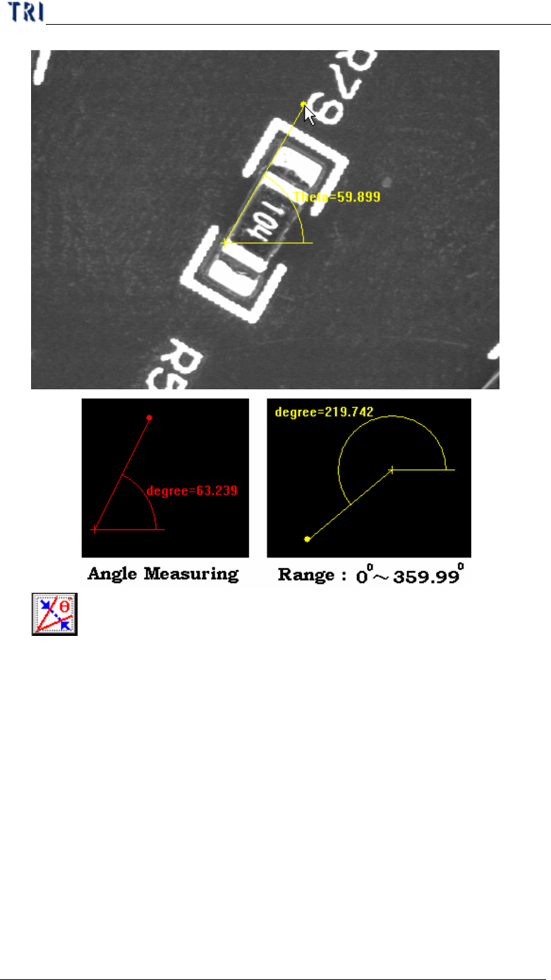
l
Angle Measuring
n It’s a tool to define the angle of components. You can use the tool to
measure the rotate for component with special angle.
Chapter 2 Manual Bar introduce
TR7500 USER MANUAL
84
l
Theta Alignment
n Since the angle measuring tool can get the number with decimal, you can
use the theta alignment to adjust the angle to be a reasonable integer.