TR7500E_Manual_en_v28.pdf - 第290页
A pp e n d i x 1 L i g h ti n g C o m p e n s a t i on T R 7500 U S E R M A N U AL 2 83 S t e p 5. M o v e t h e X - Y t a b l e t o l e t t h e c a m e r a a bo v e t h e g r a y ca r d . O r p r e s s [ M o v e T o ] b…
Appendix 1 Lighting Compensation
TR7500 USER MANUAL
282
Appendix 1 Lighting Compensation
1. Lighting Compensation
Ø This function can carry on the lighting compensation to camera with the
software. The standard is that when lighting range is established as 60mA and
intensity is 128 at all adjusted zones the gray level of the gray card image is
compensated to 100.
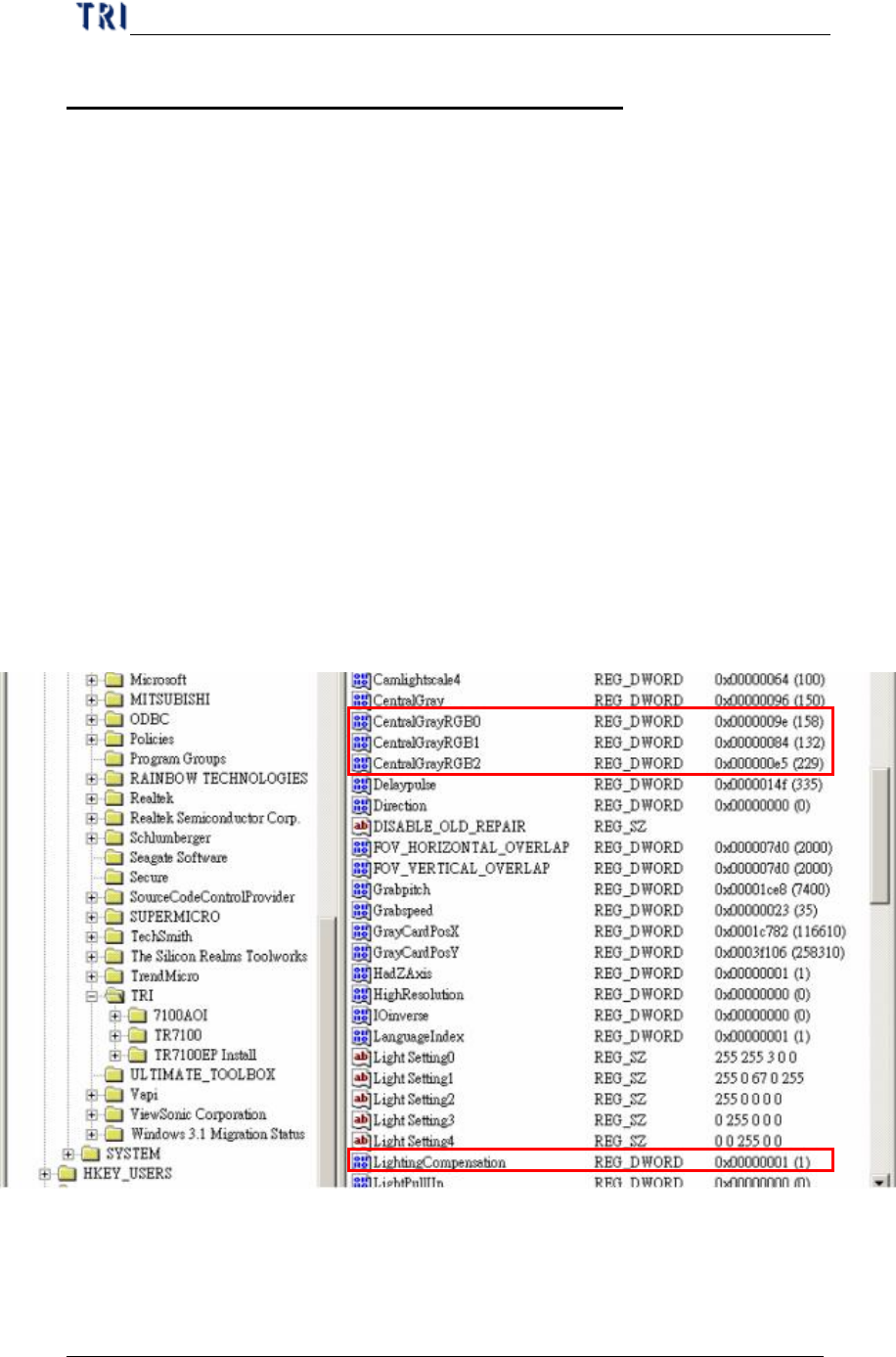
Step1. Press [Start/Run/ Key in “regedit”] to open the registry. Enter
“HKEY_LOCAL_MACHINE\HKEY_LOCAL_MACHINE\SOFTWARE\TR
I\” and check if there is a DWORD variable named “LightingCompensation”.
If there is not the variable, you can open the main program of TR7500E and
the variable is created automatically.
Step2. If you want to execute lighting compensation, you can change the value of the
variable to “1”.
Step3. When you execute the lighting at the first time, the system creates the
following 3 parameters. [CenteralGrayRGB0], [CenteralGrayRGB1],
[CenteralGrayRGB2] are represented the objective gray level for R, G, B
sensors.
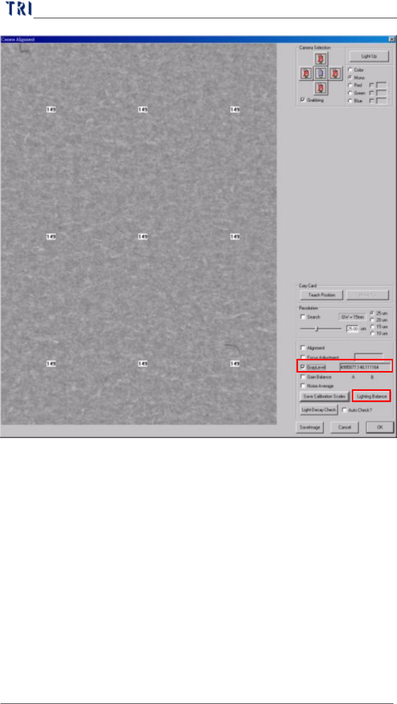
Step4. Open the mail program of TR7500E and enter [Utilities/Camera Alignment].
Appendix 1 Lighting Compensation
TR7500 USER MANUAL
283
Step5. Move the X-Y table to let the camera above the gray card. Or press [MoveTo]
button.
Step6. Select the [GrayLevel] to show the gray level of current image.
Step7. Press [Lighting Balance] button and input the password “7100” to do lighting
compensation. (Note: Be sure that the FOVs of 5 cameras are on the gray
card.)
2. Lighting Decay Auto Check
Ø The function is to test the difference between current value (before
compensating) and objective value with software.
Step1. Open the main program of TR7500E and enter [Utilities/Camera Alignment].
Step2. Move the X-Y table to let the camera above the center of gray card.
Appendix 1 Lighting Compensation
TR7500 USER MANUAL
284
Step3. Press [Light-Decay Check].
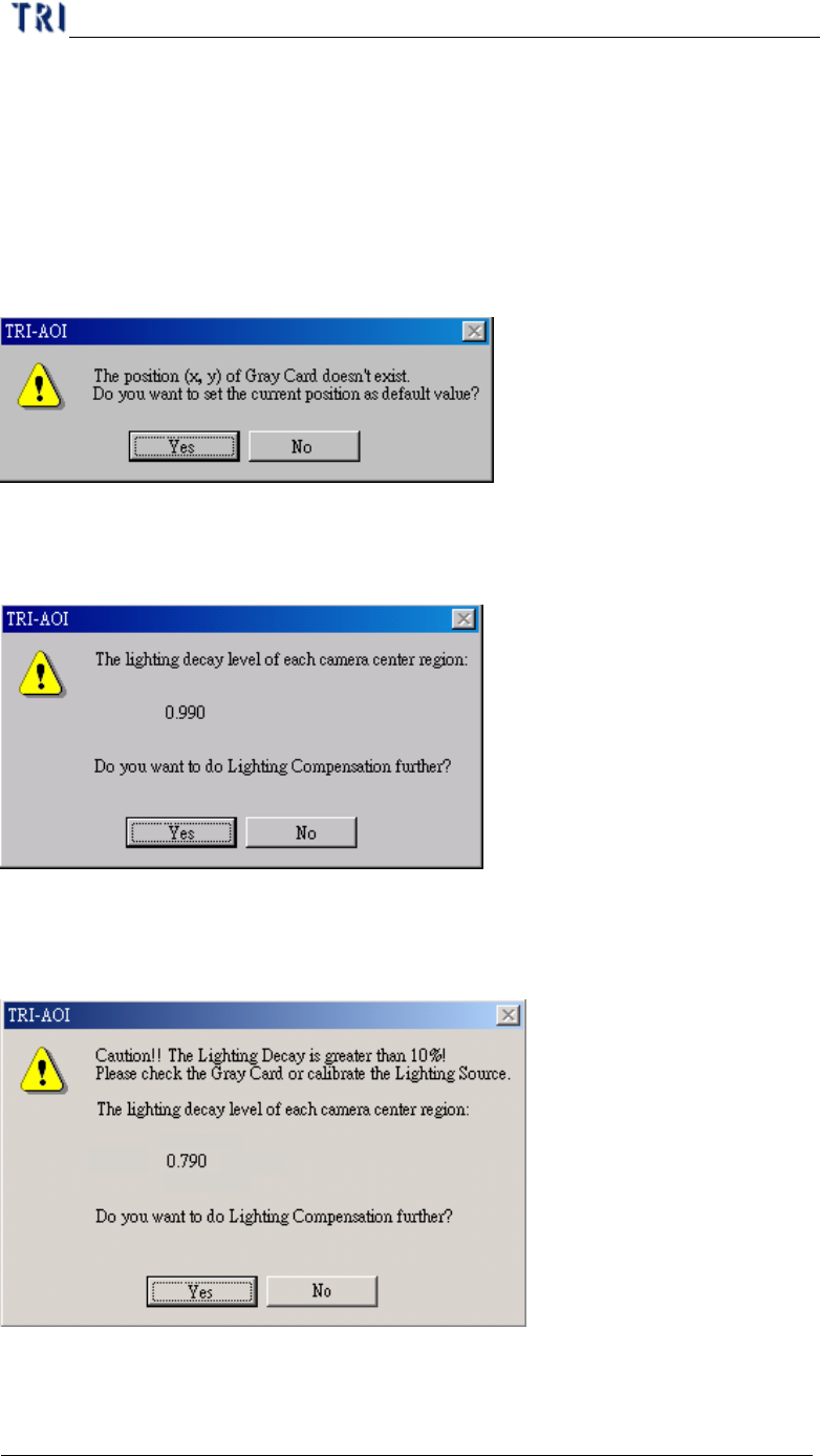
Step4. For the first time the system display the window below to ask if you want to
save the position of gray card to system. The value of X axle coordinate and Y
axle coordinate are saved in the registry and named “GrayCardPosX” and
“GrayCardPosY”. When the two variables are existing, the under window
doesn’t appear again. If you want to change the value, you can move the
cameras to be on the gray card then press [Teach Position] button.
Step5. After pressing [Light-Decay Check] button, the system will display the under
window. It displays the decay of gray level now. You can select if you want to
do lighting compensation later according to the light decay value.
Step6. If the decay is over 10% for any camera, the appeared dialog at Step5 will be
changed as the following window to remind you that the decay of lighting is
too serious.
Step7. If you select [Auto Check], the system checks the lighting decay automatically
when the program is opened.