TR7500E_Manual_en_v28.pdf - 第239页
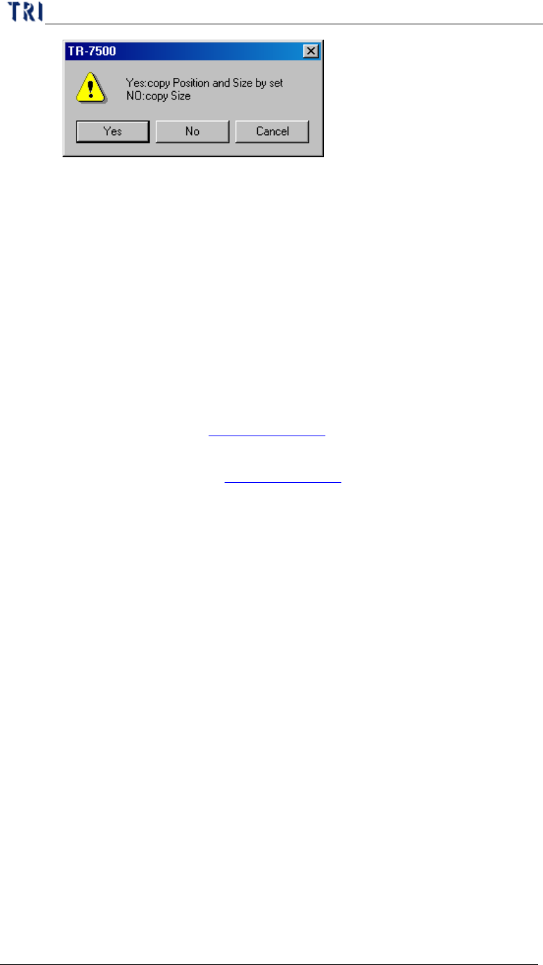
C h a p t e r 4 T r a i n d i a l og f u n c t i on T R 7500 U S E R M A N U AL 2 32 ( 2) C o p y – Y o u c a n c o p y t h e s i ze o r po s i t i o n t o t h e o t h e r c o mp o n e n t s w i t h s a m e t y p e .
Chapter 4 Train dialog function
TR7500 USER MANUAL
231
you have to select [Edit/Rotate Side] to change the direction
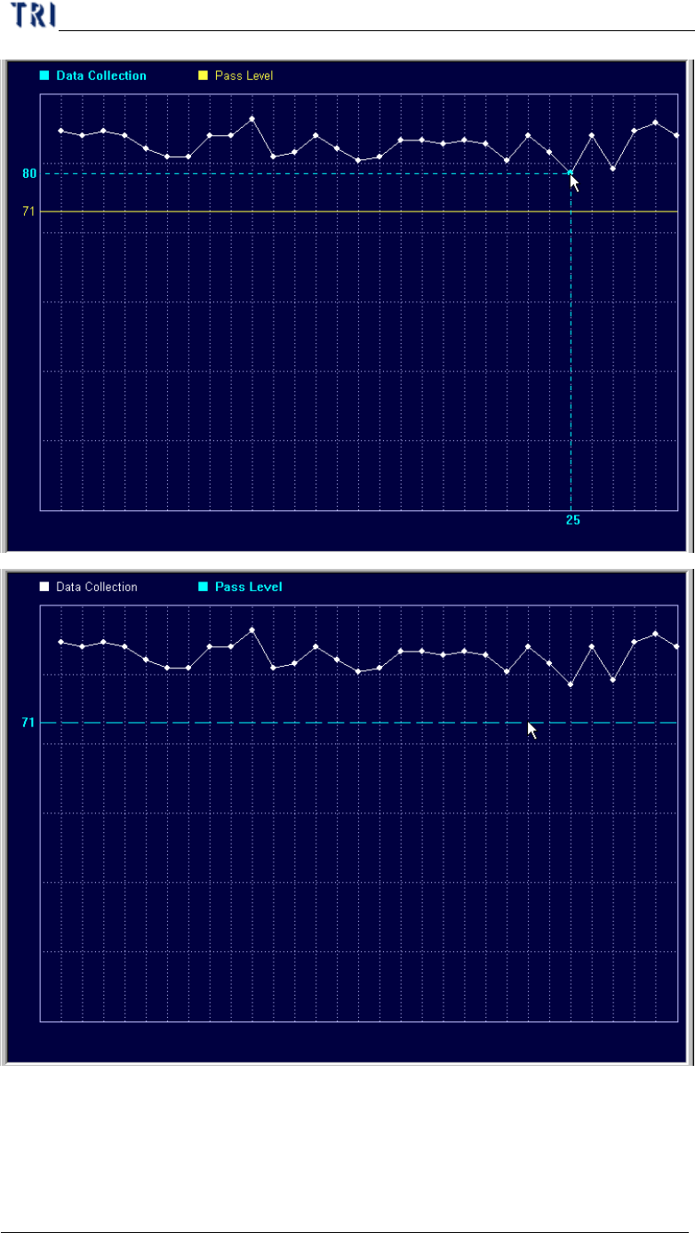
l Show Data Collection Chart of this Box – It is enabled only when you
select [Program/Auto Pass Level Setting/Inline Data Collection]. It
will show the recent 30 data. You can click the point to show the result
and drag the yellow line to change the pass level.
Chapter 4 Train dialog function
TR7500 USER MANUAL
232
(2) Copy – You can copy the size or position to the other components with
same type.
Chapter 4 Train dialog function
TR7500 USER MANUAL
233
l Yes – Copy the size and position to the relative component on the other
multi-board. If the inspection box is trained the setting can’t be
changed.
l No – Just copy the size to the other components.
(3) Save Image – Save the FOV to the folder that the SOL file saves in. The file
name is composed by date and time.
(4) Set Weighting – The View Model widow shows after pressing the button.
Then you can set the weighting for specified image. See Chapter 4 6.2.6. for
more information about “set weighting”.
(5) Link Box –You can assign windows that are parents and children to link.
See more about link in Chapter 3 10.2.2.
(6) Unlink Box – You can press [Unlink] to break the link between windows.
See more about unlink in Chapter 3 10.2.3.
(7) Copy Box – Copy the selected inspection box in the system.
(8) Cut Box – Cut the selected inspection box in the system.
(9) Paste Box – Paste the box that copy or cut before. Select a box and press
[Cut Box] or [Copy Box] first then press [Paste Box] at the objective FOV.
The inspection box does not appear now, and you have to move the mouse
to the correct position and left click on the image; then the dialog below
appeared. After you input the information of the component and press [OK],
the inspection box is visible. If there are other components in the range of
2mm near newly-increased component, it is unable to stick the inspection
box.