TR7500E_Manual_en_v28.pdf - 第18页
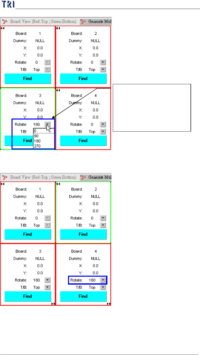
C h a p t e r 1 AO I S t a nd a r d P r o j ec t Cr ea t i on T R 7500 U S E R M A N U AL 11 ( 4) S e tt i ng b o a r d 4 r o t a t i o n . S e t t i ng C AD f i l e i n c l u d i ng bo a r d r o t a t i o n a ng l e ( 0…
Chapter 1 AOI Standard Project Creation
TR7500 USER MANUAL
10
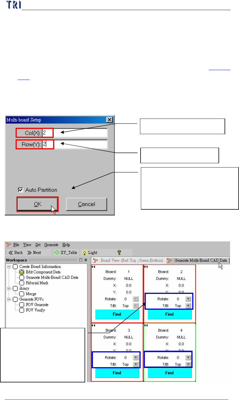
4. Generate Multi-Board CAD Data
l Since the CAD file you collect before is for single board, you have to create
multi-board data.
l If the PCB is a single board you can only input 1 in column and row field
separately and press [Next] to enter the next step, Fiducial Mark Setting (Chapter
1 5. ).
4.1. Setting Multi-board arranged information
(1) Setting Multi-Board matrix (X direction & Y direction board counting).
(2) Setting board rotation first in multi-board.
(3) Setting board 3 rotation.
Multi-board column quantity
Multi-board Row quantity
Setting first board and last board,
the system will be automatic find
the relationship between board
and b
oard
Setting CAD file including
board rotation angle (0
~270) and side (Top/Bottom)
for mapping the multi-board,
if need.
Chapter 1 AOI Standard Project Creation
TR7500 USER MANUAL
11
(4) Setting board 4 rotation.
Setting CAD file including
board rotation angle (0 ~270)
and side (Top/Bottom) for
mapping the multi-board, if
need.
Chapter 1 AOI Standard Project Creation
TR7500 USER MANUAL
12
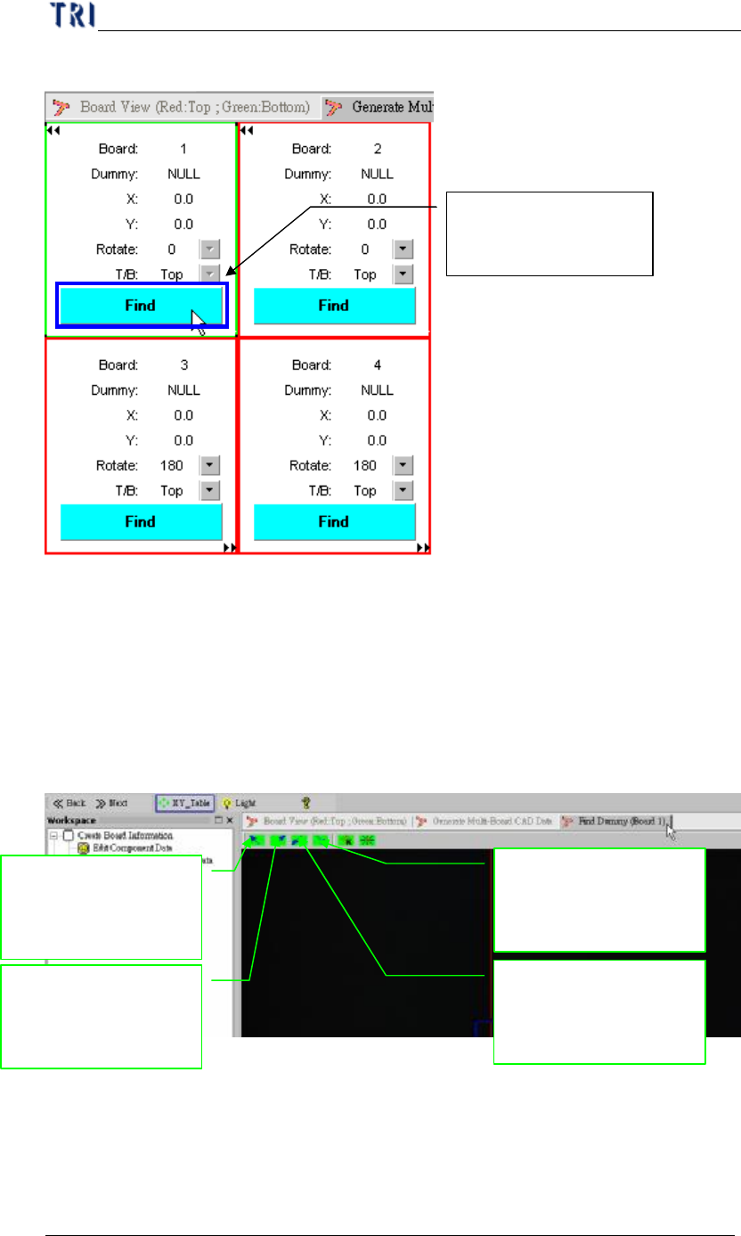
4.2. Setting board 1 first
4.3. Get Board Rotation angle
l Setting board rotation angle in board 1.
l You can get the board angle from two component on the board, that two
component have max distance is better for board angle detection.
(1) Main frame display.
(2) Set dummy component.
Setting board 1 with
CAD relationship
Moving Camera
lighting to upper-left
position of panel
Moving Camera
lighting to
upper-right position
Moving Camera
lighting to lower-left
position of panel
Moving Camera
lighting to lower-right
position of panel