TR7500E_Manual_en_v28.pdf - 第134页
C h a p t e r 3 A O I A T P G F u n c t i o n i n s t r u c t i on T R 7500 U S E R M A N U AL 1 27 ( 1 1) T r a n s l a t e – S t a r t t o t r a n s l a t o r C AD f il e t o A O I f i l e . ( 1 2) Q u it – E x i t i n…
Chapter 3 AOI ATPG Function instruction
TR7500 USER MANUAL
126
1
2
3
4
5
6
7
8
9
10
11
12
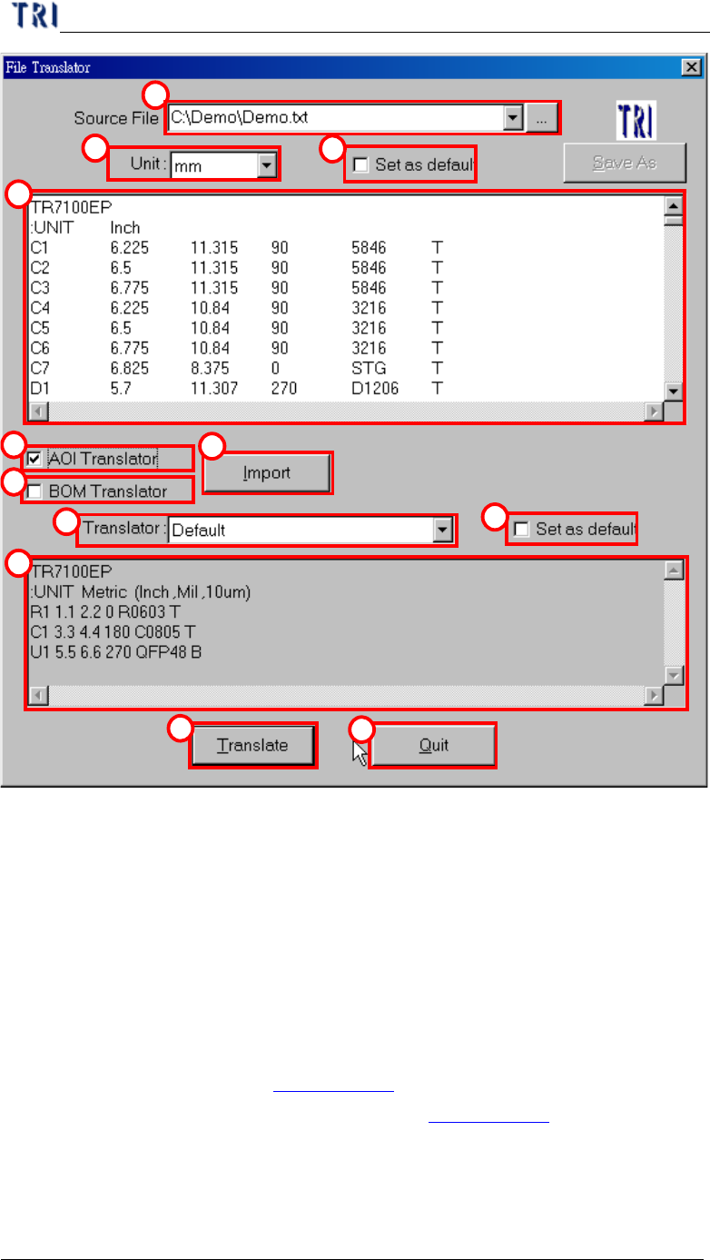
(1) Source file – Input the path of original CAD file.
(2) Unit – Define translate unit that must be the same as CAD file.
(3) Set as default – Used current unit setting as default.
(4) Message windows – Display the source file contents.
(5) AOI Translator – Check to translate CAD to AOI file.
(6) BOM Translator – Check to translate information of bill of material to BOM file.
Since the bom format for all corporations are different the converter may not be
suitable for all boms. In this case we suggest that it’s better to create the BOM
file with hands (See section Chapter 3 1.1. ).
(7) Import – Input translator program (See section Chapter 3 1.3. ).
(8) Translator – Choosing translator program.
(9) Set as default – Used current translator setting as default.
(10) Message windows – Display the standard form of the translator for example.
Chapter 3 AOI ATPG Function instruction
TR7500 USER MANUAL
127
(11) Translate – Start to translator CAD file to AOI file.
(12) Quit – Exiting the translator procedure.
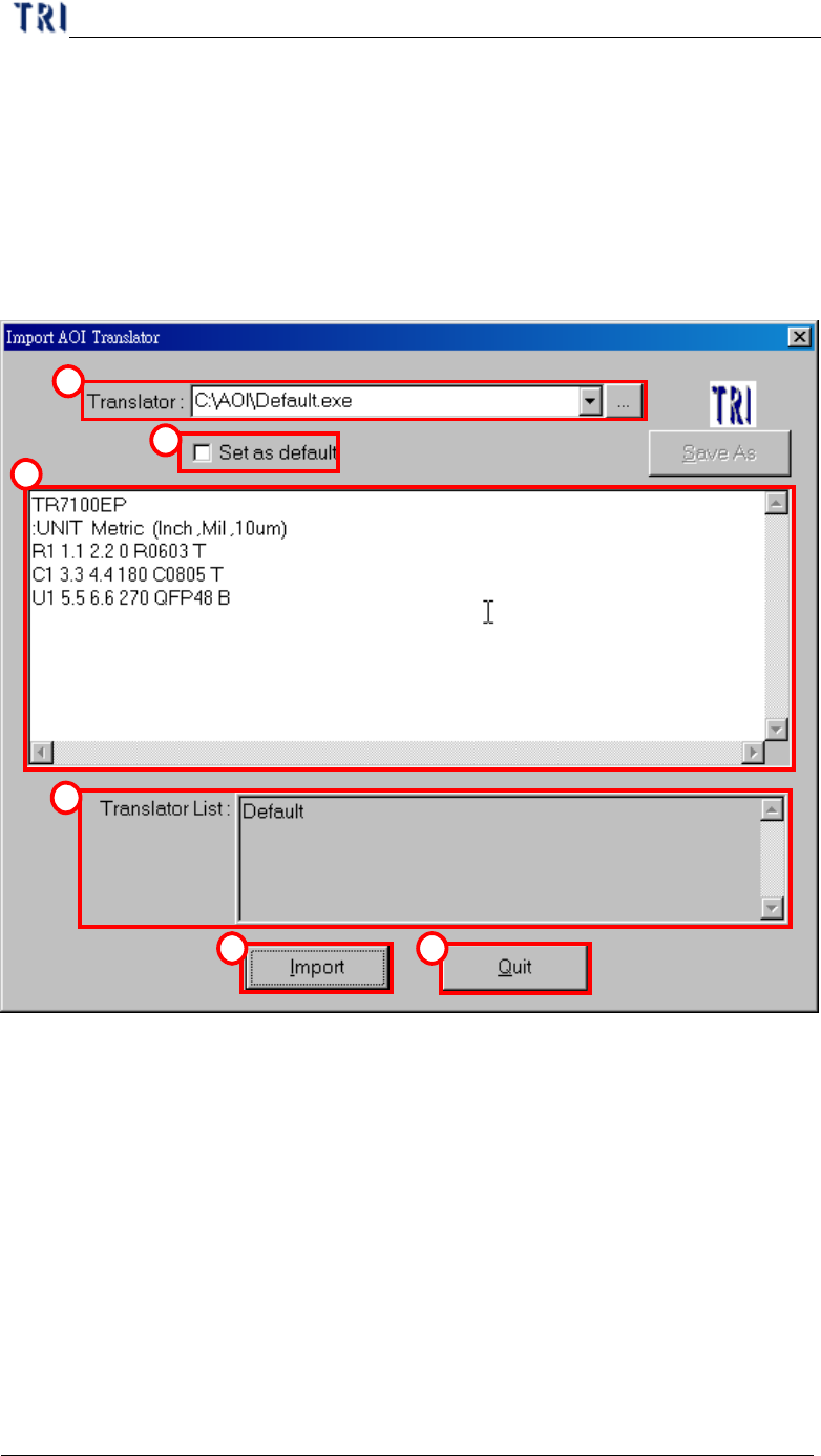
1.3. Import
In section 1.2. , press “Import” in “File translator” dialog, then you will enter
“Import AOI Translator” dialog as the following.
1
2
3
4
5 6
(1) Translator – Input or add a new translator file.
(2) Set as default –Used current translator file as default.
(3) Message windows –Display the standard form of the translator for example.
(4) Translator list – All translator lists in the system.
(5) Import – Loading the new translator.
(6) Quit – Exiting translator import.
Chapter 3 AOI ATPG Function instruction
TR7500 USER MANUAL
128
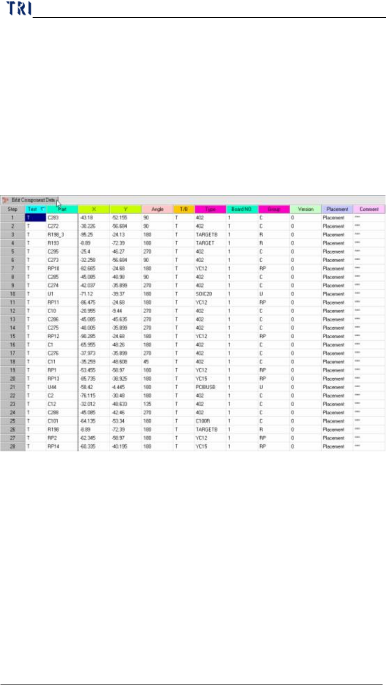
2. Edit Component Data
l Mainframe for editing component data. The meanings of all fields from left to
right are: test or not, component name, X coordinate, Y coordinate, component
angle, top or bottom side, component type, board number and group of the
component (the system separates the group automatically according to the
beginning characters of the component; you also can define the group manually
in the 7
th
field of AOI file.)
l When right clicking on the main frame, the pop-up menu will show. The
meanings of the tools will be explained later.
2.1. Board View
l Display the component position on the board from AOI file loading.