TR7500E_Manual_en_v28.pdf - 第241页
C h a p t e r 4 T r a i n d i a l og f u n c t i on T R 7500 U S E R M A N U AL 2 34 ( 1 0) M o v e t o L e f t F O V – M o v e t h e s e l e c t e d b o x t o t h e l e f t F O V . ( 1 1) M o v e t o R i g h t F O V – M…
Chapter 4 Train dialog function
TR7500 USER MANUAL
233
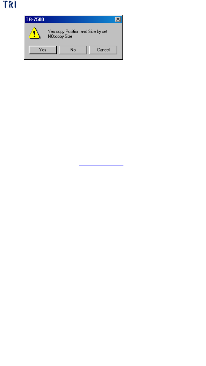
l Yes – Copy the size and position to the relative component on the other
multi-board. If the inspection box is trained the setting can’t be
changed.
l No – Just copy the size to the other components.
(3) Save Image – Save the FOV to the folder that the SOL file saves in. The file
name is composed by date and time.
(4) Set Weighting – The View Model widow shows after pressing the button.
Then you can set the weighting for specified image. See Chapter 4 6.2.6. for
more information about “set weighting”.
(5) Link Box –You can assign windows that are parents and children to link.
See more about link in Chapter 3 10.2.2.
(6) Unlink Box – You can press [Unlink] to break the link between windows.
See more about unlink in Chapter 3 10.2.3.
(7) Copy Box – Copy the selected inspection box in the system.
(8) Cut Box – Cut the selected inspection box in the system.
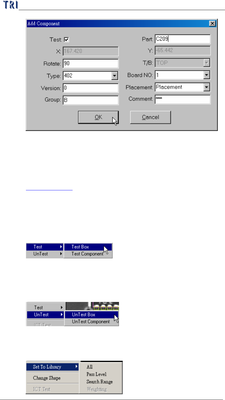
(9) Paste Box – Paste the box that copy or cut before. Select a box and press
[Cut Box] or [Copy Box] first then press [Paste Box] at the objective FOV.
The inspection box does not appear now, and you have to move the mouse
to the correct position and left click on the image; then the dialog below
appeared. After you input the information of the component and press [OK],
the inspection box is visible. If there are other components in the range of
2mm near newly-increased component, it is unable to stick the inspection
box.
Chapter 4 Train dialog function
TR7500 USER MANUAL
234
(10) Move to Left FOV – Move the selected box to the left FOV.
(11) Move to Right FOV –Move the selected box to the right FOV..
(12) Rotate Box Side – Rotate the pin direction with 90 degrees of
counterclockwise for clicking once.
(13) Set Logic – Set the Logic between windows. See more about logic in
Chapter 3 10.7.1. .
(14) Inverse Logic – Checks this item to start the [Inverse Logic] function. After
you select this function, the system regards a box that is passing the pass
level as failed and a box that is not passing the pass level as passed.
(15) Test – Set the selected inspection box as [Test Box] or [Test component].
It establishes it with [untest] correspond to
(16) Untest –Set the selected inspection box as [UnTest Box] or [UnTest
component]. [UnTest Box] means only set the selected box as untested and
the box become blue; [UnTest Component] means set the all boxes in
selected component as untested and the boxes become gray.
(17) Set to Library – Sent the information of [Pass Level] or [Search Range] of
the selected box to Library. You can only select the inspection boxes that is
belonging to a component. And [Weighting] is only for TR7500E series.

Chapter 4 Train dialog function
TR7500 USER MANUAL
235
(18) Change Shape – The function is to change the window shape from square to
circle or from circle to square. It only works for [Void] or [Solder] window.
5.2. The boxes in FOV image
l Purple – Multi-function window. You can select a [Missing/Missing Polarity] or
[Lead] box and double click on the multi-function window. The multi-function
window will be moved to the selected window.
l Orange – Untrained box.
l Dark blue – Untested inspection window.
l Gray – Untested component.
l Red – Selected box. You can double click one box and the system will selected
the all inspection boxes that are linked with selected box automatically.
l Light blue – The inspection boxes in other FOVs.
l Light purple – [Missing/Missing Polarity] or [Lead]
l Light green – Inspection boxes except [Missing/Missing Polarity/Lead].
6. Function Area
6.1. Function Frame
l You can click the train dialog then press [F1] to change the characters of button
to hot keys. Press once again and switch over.