TR7500E_Manual_en_v28.pdf - 第95页
C h a p t e r 2 M a nu a l B a r i n t r o d u ce T R 7500 U S E R M A N U AL 88 1. U s e bo x t oo l t o s e t t h e c o m po n e n t 3. S e l e c t [ B y C o mp o n e n t ] t h e n p r e ss [ C AD ( 0 , 0 ) ] 2. S e l …
Chapter 2 Manual Bar introduce
TR7500 USER MANUAL
87
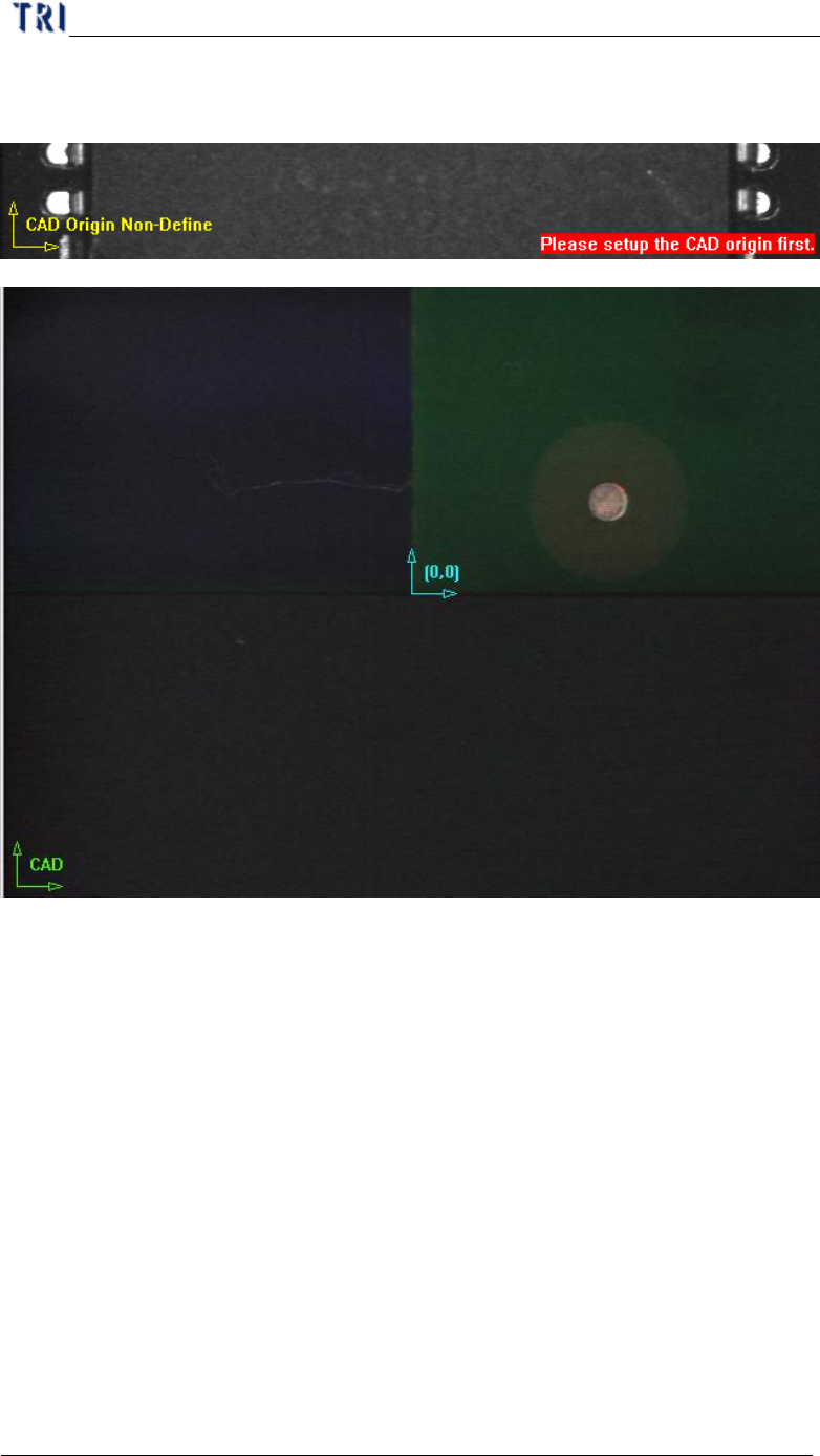
established the icon is changed to green and the origin is marked as blue icon.
There are two ways to set origin.
l By Mouse Drop - You can use the method when editing a new CAD file.
Move box or cross line tool to the position which you want to set on then press
[CAD(0,0)] and the system will record the coordinates of the origin.
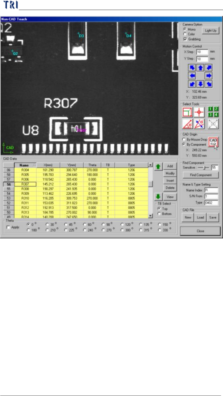
l By Component - You can use the method when loading an existing AOI file
for continuous editing. Select a component at component list field and move a
tool to the component center. Press [CAD(0,0)] button then the system will
record the coordinates of the origin.
Chapter 2 Manual Bar introduce
TR7500 USER MANUAL
88
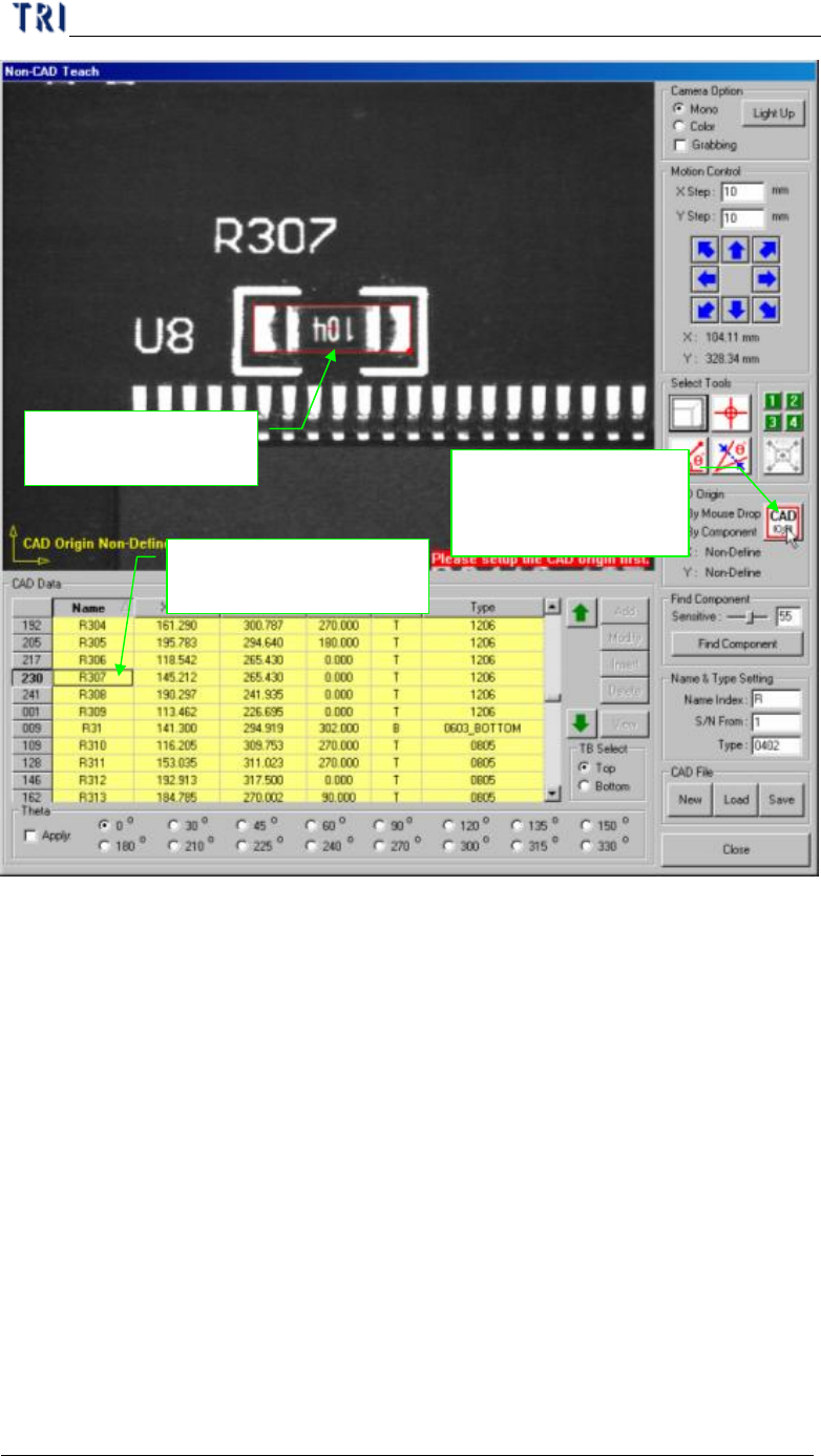
1. Use box tool to set
the component
3. Select [By
Component] then
press [CAD(0,0)]
2. Select the component
in the table
Chapter 2 Manual Bar introduce
TR7500 USER MANUAL
89
(5) Find Component - You can use the function to create components which is
similar with standard image.