TR7500E_Manual_en_v28.pdf - 第78页
C h a p t e r 2 M a nu a l B a r i n t r o d u ce T R 7500 U S E R M A N U AL 71 l M a x F a i l I m a g e C o u n t – T h i s i s t h e m a x i m u m n u m b e r o f f a il e d i m a g e t h a t A O I wil l t r a n s f …
Chapter 2 Manual Bar introduce
TR7500 USER MANUAL
70
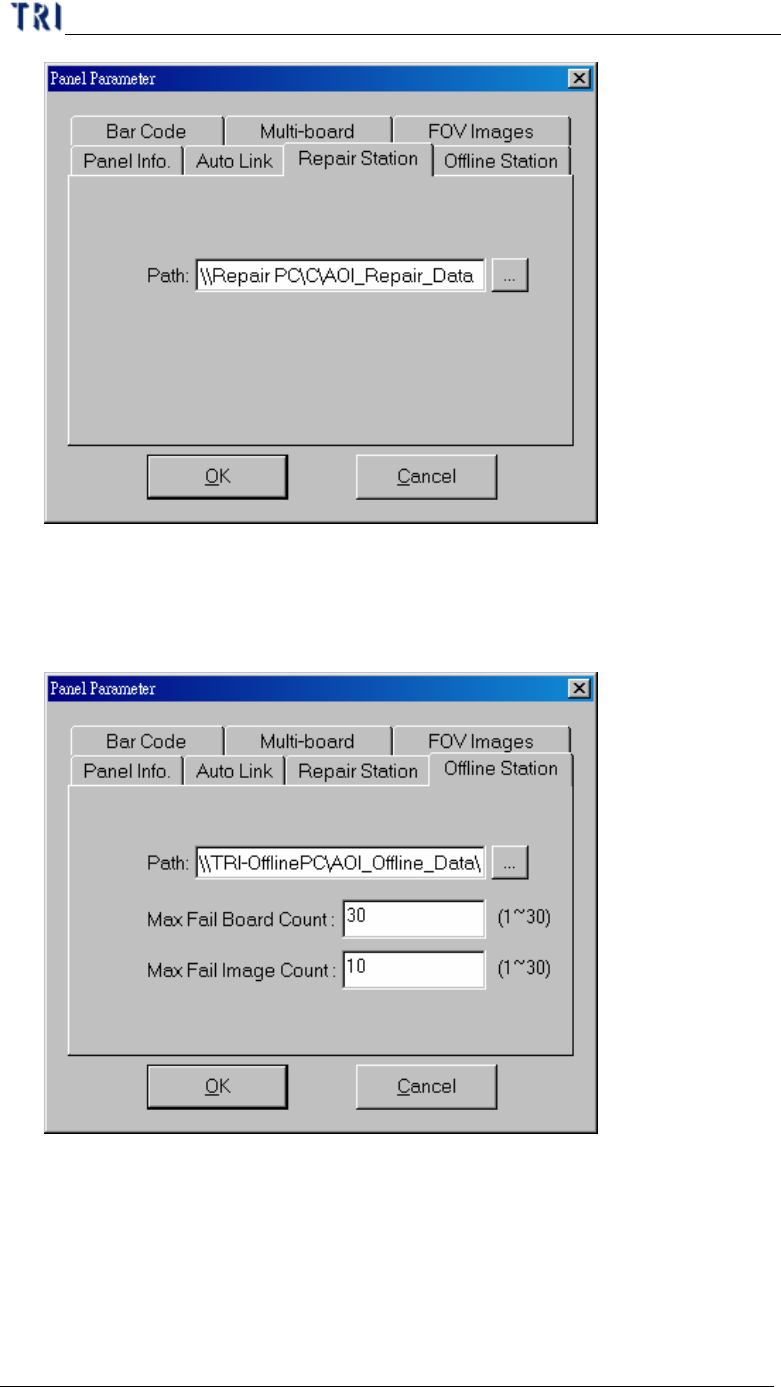
l Path – Setting repair data saving path for repair station. It is set as
[\\RepairPC\C\AOI_Repair_Data] usually.
3.3.6. Offline Editor
l Path – Setting offline data saving path for offline editor. It is set as
[\\OfflinePC\C\AOI_Offline_Data] usually.
l Max Fail Board Count – This is the maximum inspecting number that the Offline
Editor can save. It means that the Offline Editor saves the latest 30 data only
when you set 30 in this field.
Chapter 2 Manual Bar introduce
TR7500 USER MANUAL
71
l Max Fail Image Count – This is the maximum number of failed image that AOI
will transfer to Offline Editor. It means that AOI only transfers the former 10
failed images to Offline for every one inspection when you set 10 in this field.
l See Chapter 8 for more information about Offline Editor.
3.4. 2D Barcode
l It can read 2D barcode information after this item is enabled. The function is still
under construction.
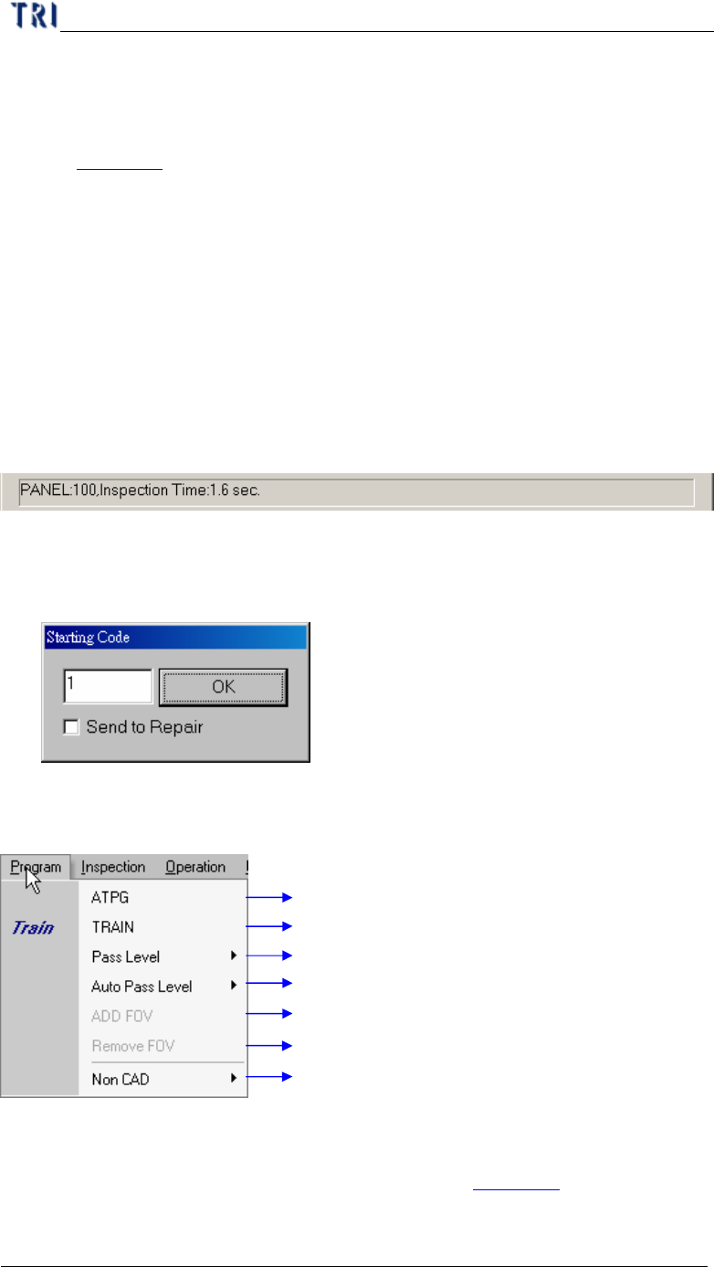
3.5. Assign Serial Code
l The function is usually used where there is no barcode on the PCB. You can
assign the serial number for PCB and the serial number can show on the result
dialog or translate to Repair Station.
l Input the initial number first then press [OK] to start this function.
l [Send to Repair] – When you select this item, the serial number is sent to Repair
Station and located on [BarcodeSN] field.
4. Program
Automatic testing program generator process
Train Process for project file adjustment
Setting for component inspection tolerance
Auto adjust inspection pass range (default 30 pieces panel)
Enable FOV when CAD file component is not setting
Disable FOV when CAD file component is setting
Create AOI Component list file by manual mode
4.1. ATPG
l Press to enter the ATPG flow. You can see details in Chapter 3 .
Chapter 2 Manual Bar introduce
TR7500 USER MANUAL
72
4.2. TRAIN
l Press to enter the train dialog. You can see details in Chapter 4 .
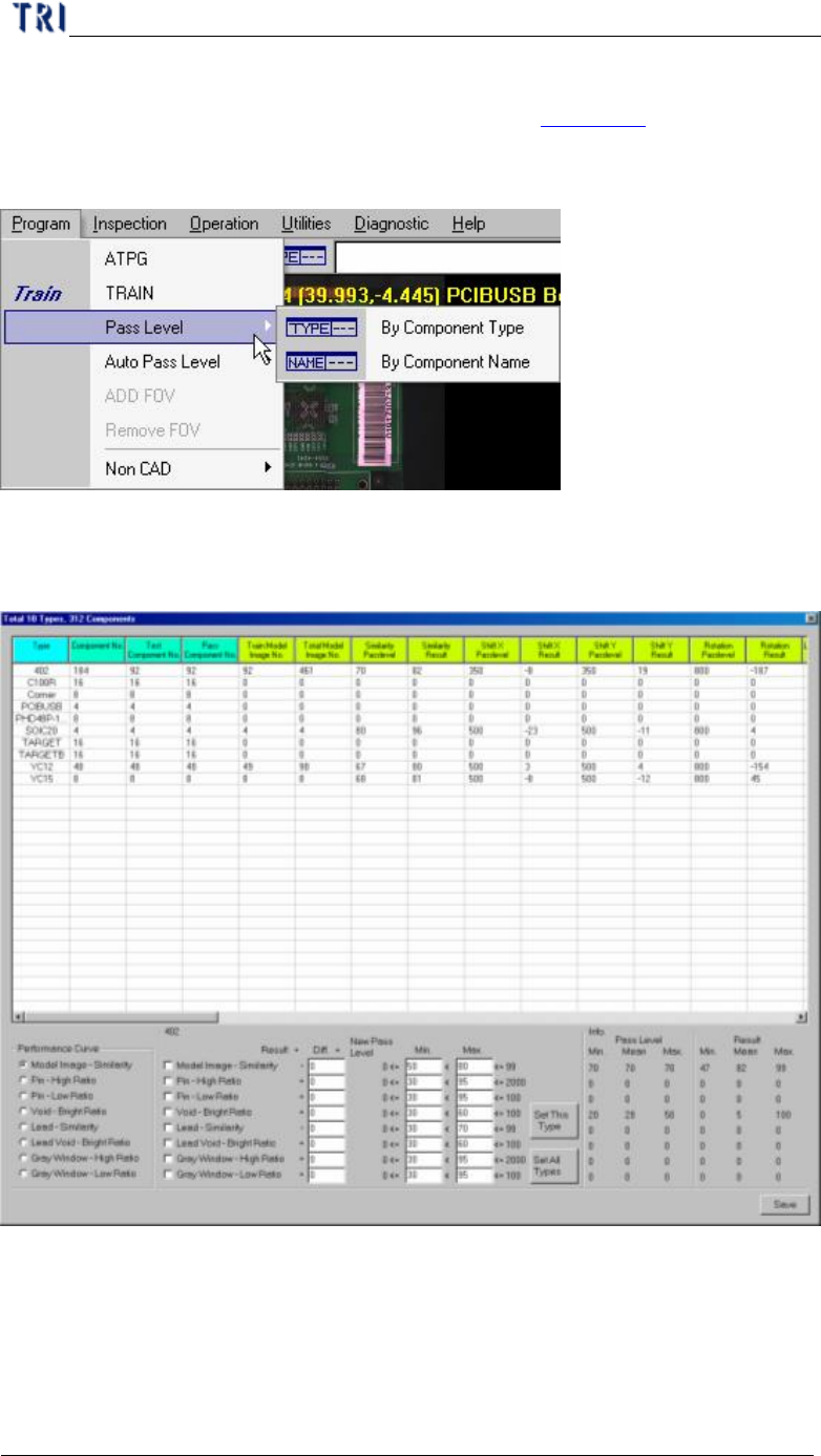
4.3. Pass Level
4.3.1. By Component Type
l Set the pass level by component type. Select then the following window present.
l In the table the former four columns mean the component information and the
following columns show the information of different inspection boxes. You can
double click on the inspection result cell to edit the pass level.