TR7500E_Manual_en_v28.pdf - 第228页
C h a p t e r 3 A O I A T P G F u n c t i o n i n s t r u c t i on T R 7500 U S E R M A N U AL 2 21 S t e p 3. [ G e n e r a t e M u l t i - B o a r d C AD D a t a ] – S e l e c ti n g [T / B ] a n d [ R o t a t e ] r e …
Chapter 3 AOI ATPG Function instruction
TR7500 USER MANUAL
220
11.4. Structure of inspection boxes
l Inspection box lying in the upper strata can help to locate the inspection box in
the lower floor.
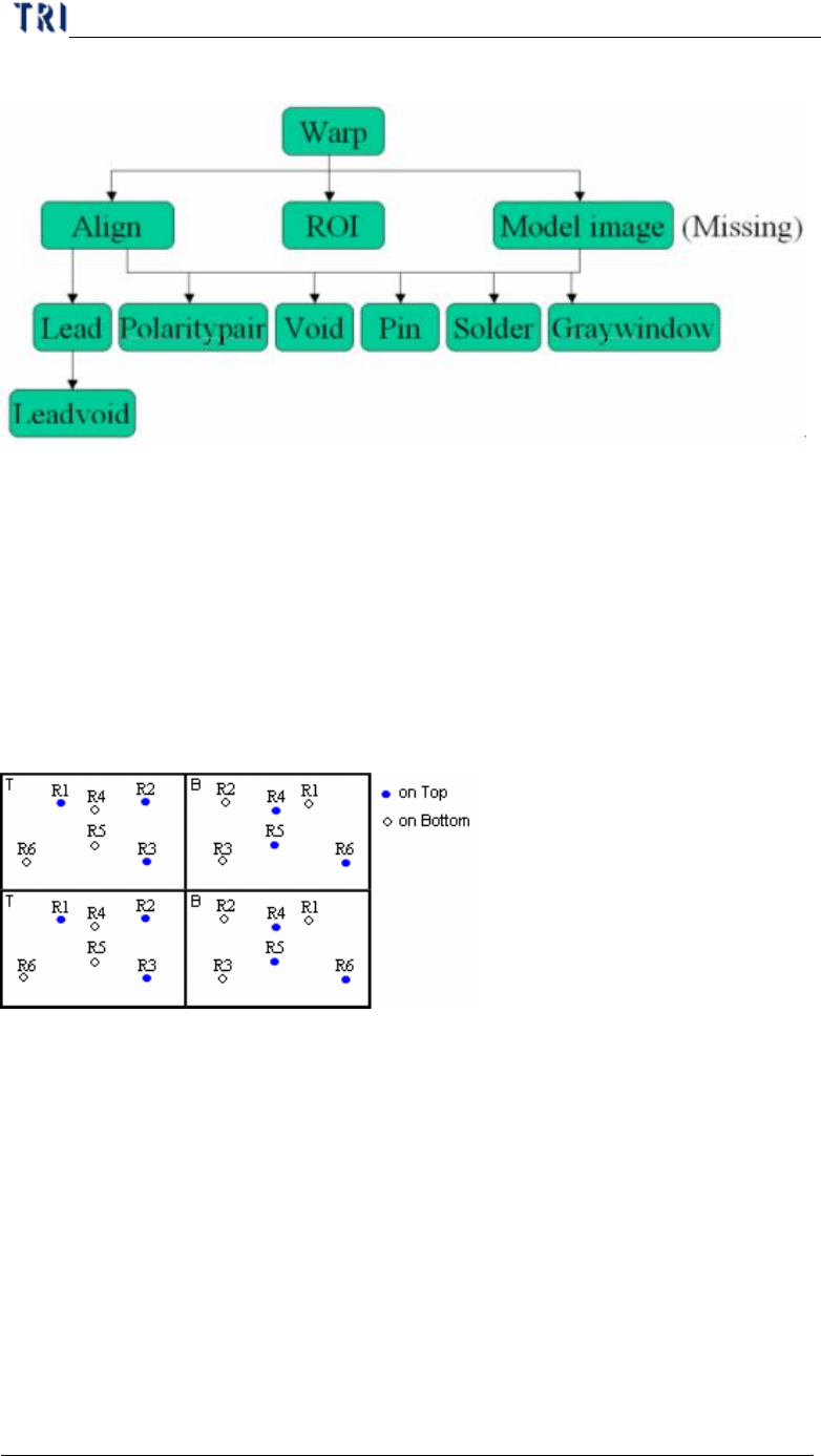
12. Principles for Top and Bottom of the Same Plane
12.1. CAD file arrangement
l The CAD must have both coordinates of top components and perspective
coordinates of bottom components.
12.2. Program Generating Procedure
Step1. Load CAD file.
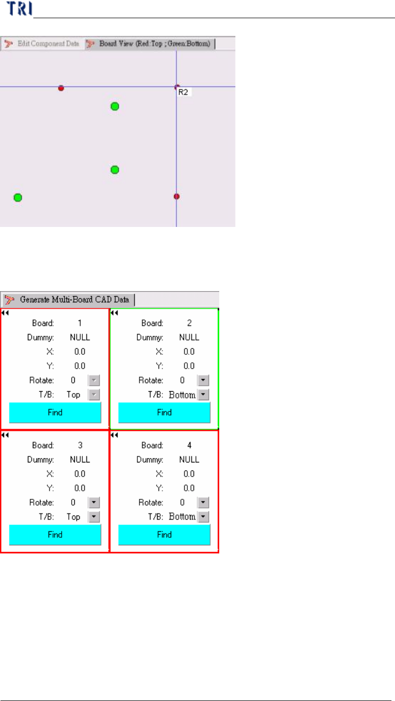
Step2. [Edit component Data] – Edit the CAD data to make it displays correct
coordinates of top components and the perspective coordinates of bottom
components regarding Board 1.
Chapter 3 AOI ATPG Function instruction
TR7500 USER MANUAL
221
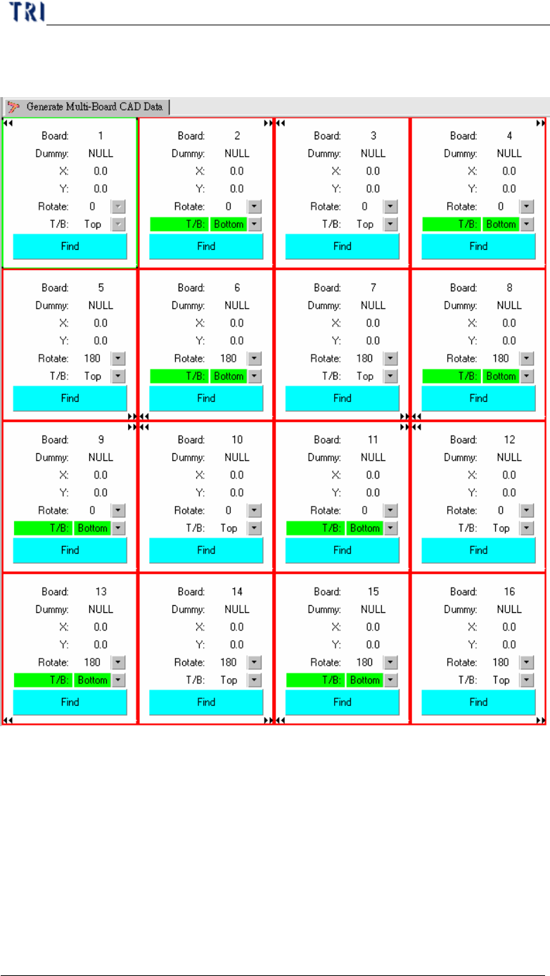
Step3. [Generate Multi-Board CAD Data] – Selecting [T/B] and [Rotate] regards the
board 1.
Step4. Find Dummy Component Position – When finding the dummy point for board
2 and board 4, you have to select the component that at the upper side. For the
example, that is R4, R5 or R6.
Step5. After generating multi-board data, you can use [Board View] function to
review the component on upper side.
Step6. Do the nest step for following standard rule.
Chapter 3 AOI ATPG Function instruction
TR7500 USER MANUAL
222
12.3. Example for Multi-boards with different side and angle
Step1. First set the dummy point for Board 1 and Board 12. Then Board 3 and Board
10 will be created automatically.