TR7500E_Manual_en_v28.pdf - 第195页
C h a p t e r 3 A O I A T P G F u n c t i o n i n s t r u c t i on T R 7500 U S E R M A N U AL 1 88 S t e p 4. Gi v e t h e n e w l o g i c s e t t i n g a n a m e , a n d i n p u t it i n [ D e f e c t ] f i e l d . T h…
Chapter 3 AOI ATPG Function instruction
TR7500 USER MANUAL
187
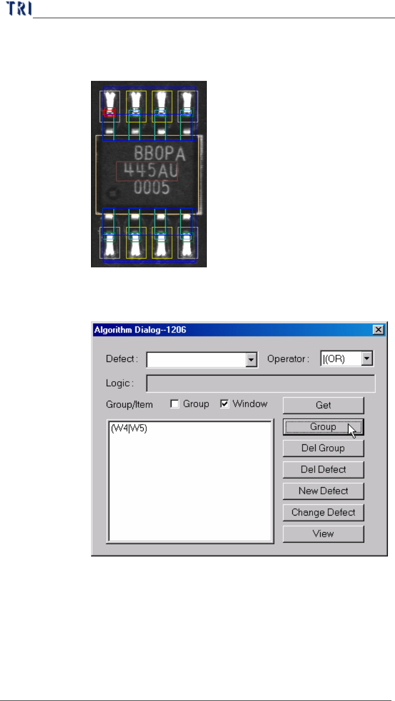
Step1. Select the inspection boxes that you want to set logic on. (You
may press [Ctrl] on keyboard and click on the boxes to select
them.)
Step2. After selecting an [Operator], checking [Window] and pressing
[Group], the inspection boxes will be composed by the specified
Operator and be listed on the window below.
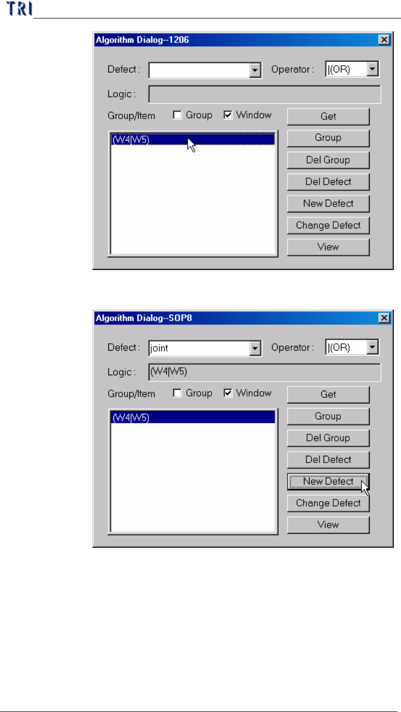
Step3. Double click on the formula that is listed on the window and the
formula will be copied on [Logic] field.
Chapter 3 AOI ATPG Function instruction
TR7500 USER MANUAL
188
Step4. Give the new logic setting a name, and input it in [Defect] field.
Then press [New Defect] to create the new logic.
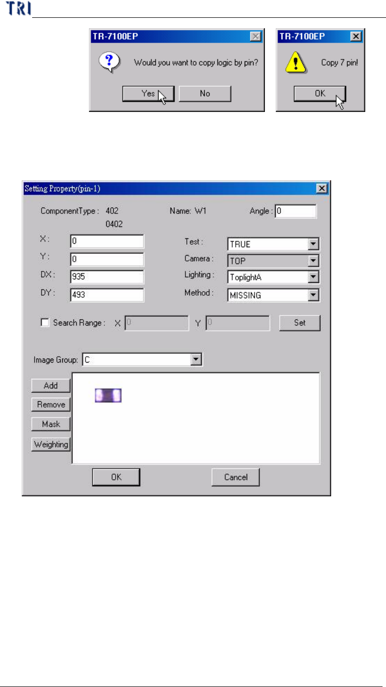
Step5. When the logic contains an inspection box that is belonging to an
IC lead, the system will ask you if you want to copy the same
logic to the other leads. You can select Yes or No according to the
situation.
Chapter 3 AOI ATPG Function instruction
TR7500 USER MANUAL
189
10.7.2. Property
l Set property of inspection box.
l (pin-1) – Displays the serial number of the IC pin that the selected
inspection box inspects. When showing (pin-1), it means that the selected
box doesn’t inspect any IC pin.
l Component Type – Displays the component type
l Name – Displays the inspection box name
l Angle – Displays the rotation angle of the component. When the angle
defined in CAD file, you can modify it here.
l X – Component on the X coordinate position.
l Y – Component on the Y coordinate position.
l DX – The component X coordinate on the center.