TR7500E_Manual_en_v28.pdf - 第256页
C h a p t e r 4 T r a i n d i a l og f u n c t i on T R 7500 U S E R M A N U AL 2 49 a n d Y a x i s c o o r d i n a t e S t e p 3. P r e s s [ O K ] t o f i n i s h t h e s e t ti ng . S t e p 4. P r e s s [ M e r g e ]…
Chapter 4 Train dialog function
TR7500 USER MANUAL
248
boxes that is linked with the objective boxes, the linked boxes will be created at
the same time.
6.2.10. Set Logic
l Set the Logic between windows. See more about logic in Chapter 3 10.7.1. .
6.2.11. Setting
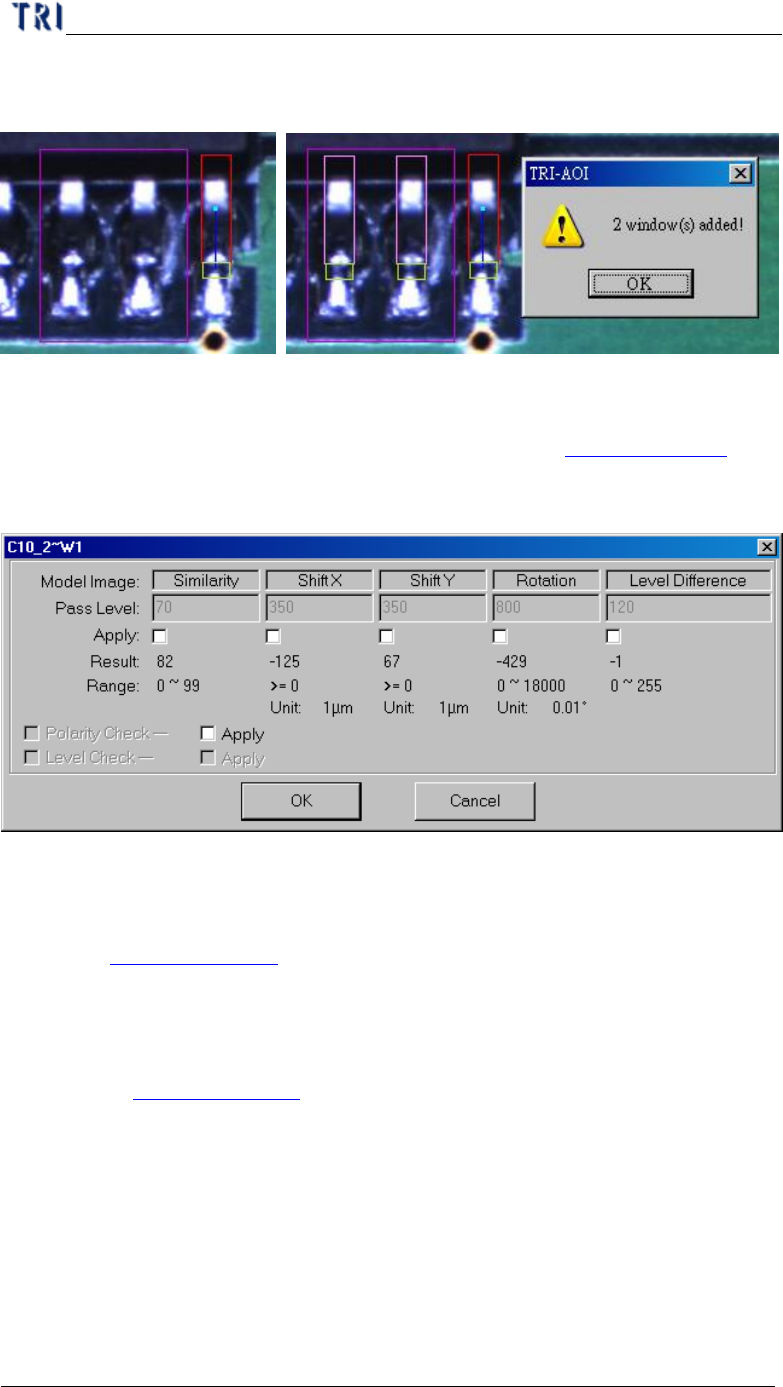
l Set the pass level for selected inspection window.
6.2.12. Link
l You can assign windows that are parents and children to link. See more about
link in Chapter 3 10.2.2.
6.2.13. UnLink
l You can press [Unlink] to break the link between windows. See more about
unlink in Chapter 3 10.2.3.
6.3. New Comp & Reset Win.
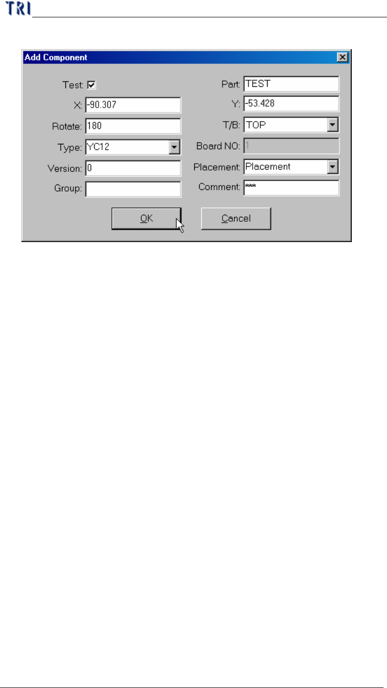
6.3.1. New Comp.
l Add a new component in the project and the component data add in AOI file too.
l Setting steps
Step1. Move multi-function window to the center of the component.
Step2. Press [New Comp.] button. You should input each information except X
Chapter 4 Train dialog function
TR7500 USER MANUAL
249
and Y axis coordinate
Step3. Press [OK] to finish the setting.
Step4. Press [Merge] to merge the library.
Step5. Capture the FOV images again.
Step6. Enter [Train] dialog to edit the component.
6.3.2. Reset Win.
l Reset the size and position of multi-function window.
Chapter 4 Train dialog function
TR7500 USER MANUAL
250
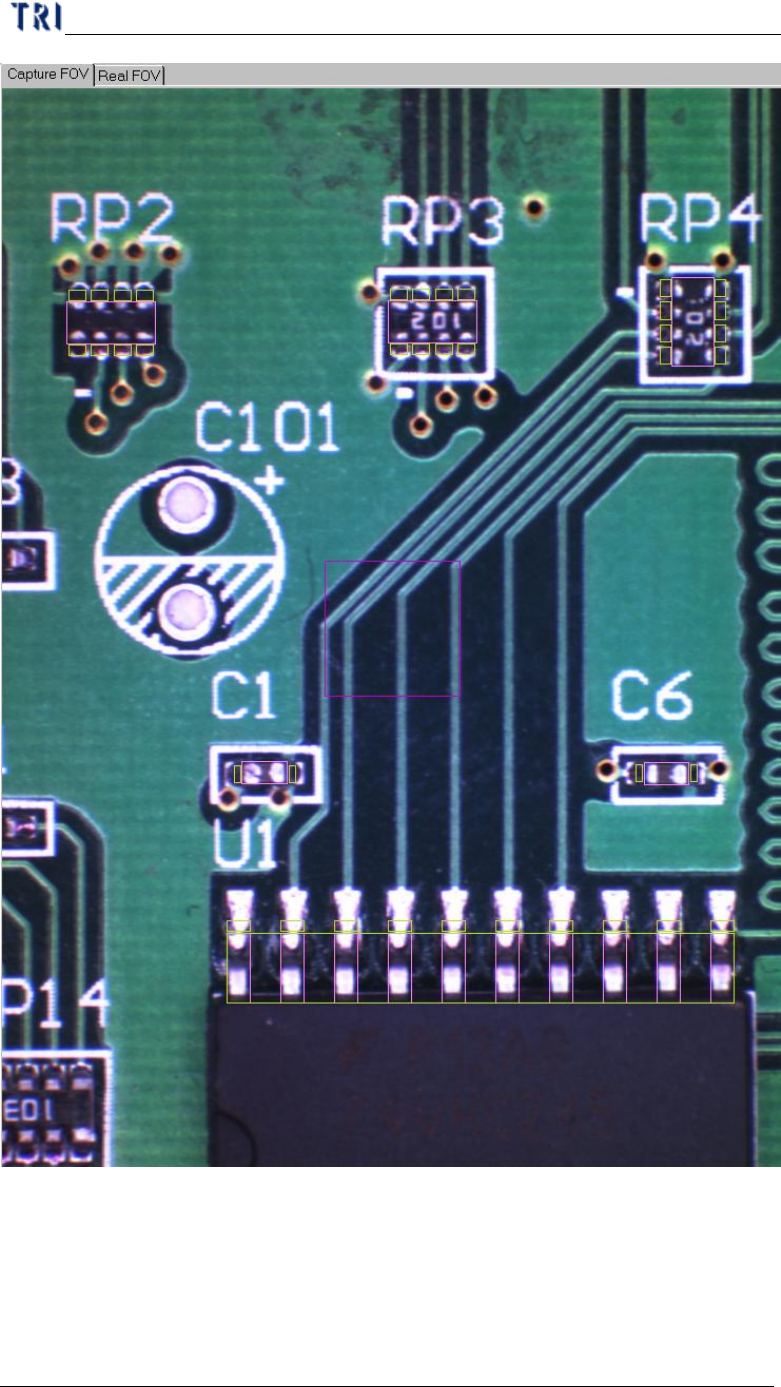
6.4. Warp Setting
6.4.1. Setwarp/Delwarp
l Set a [Warp] for the current FOV. Move the multi-function window to the
suitable position and adjust the size. Then press [Setwarp] to set a warp window.