TR7500E_Manual_en_v28.pdf - 第207页
C h a p t e r 3 A O I A T P G F u n c t i o n i n s t r u c t i on T R 7500 U S E R M A N U AL 2 00 y o u s a v e t h e l i b r a r y , t h e c u rr e n t s i ze wil l b e s a v e d . 10 . 9 . E xa m pl e f o r e di t i …
Chapter 3 AOI ATPG Function instruction
TR7500 USER MANUAL
199
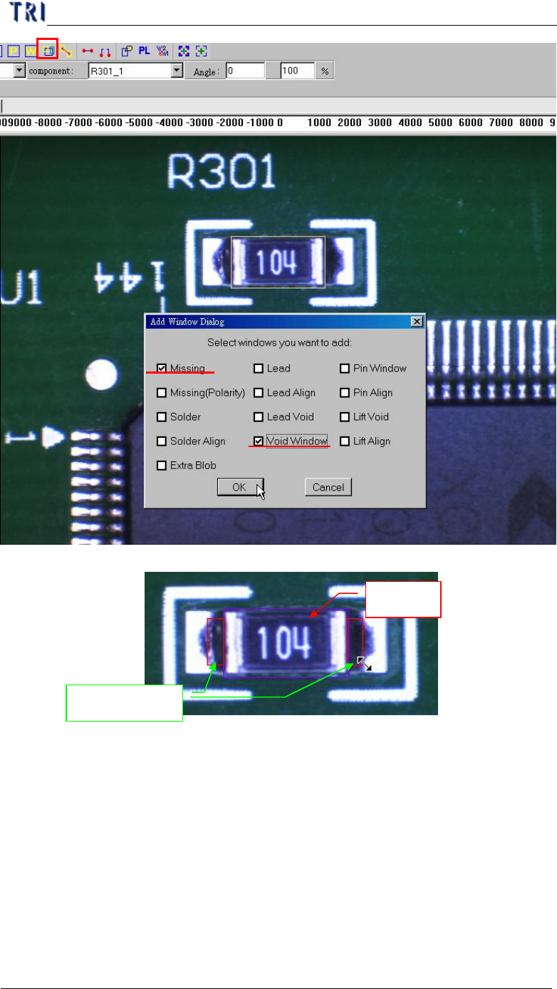
Only missing
box can be
selected
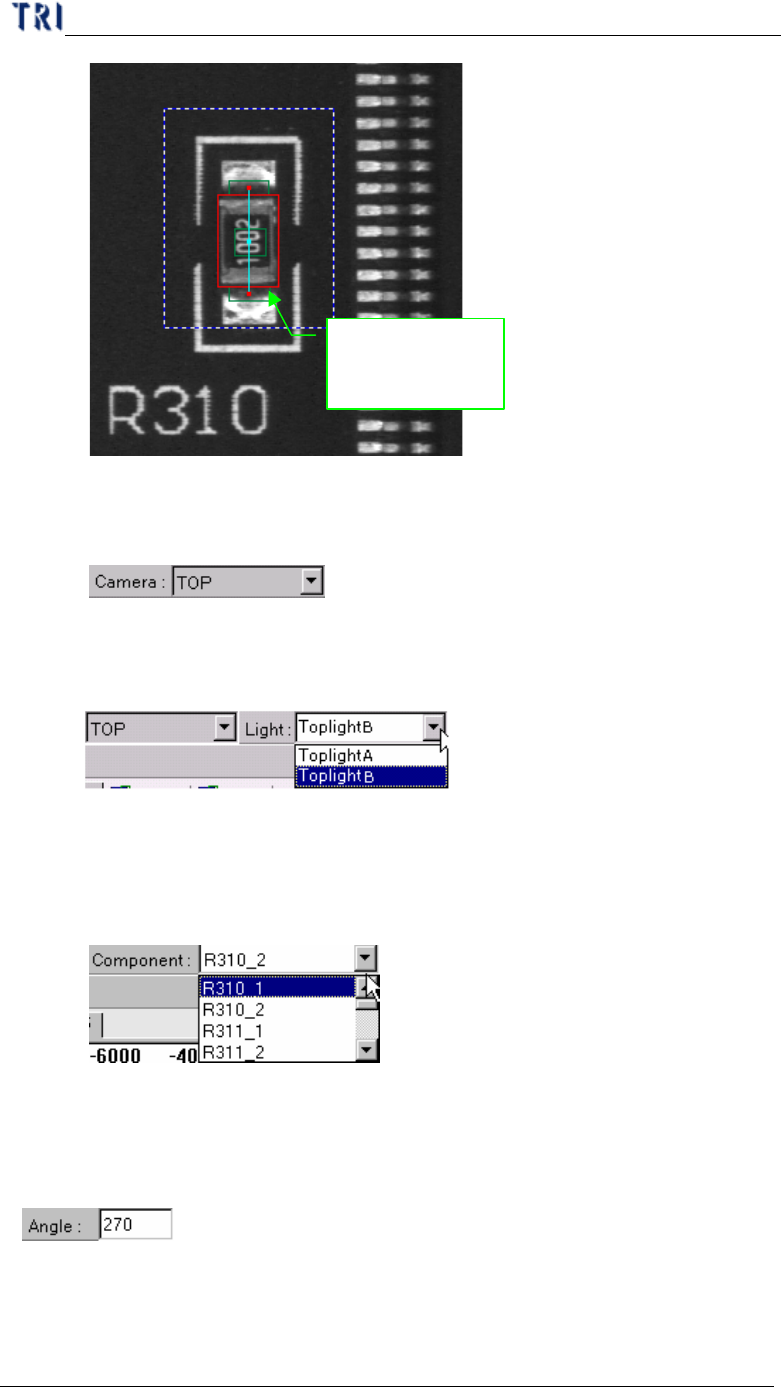
10.8.4. Camera
l To display with top camera.
10.8.5. Light
l You can choose specific light to display.
10.8.6. Component
l You can select any component in this type according to CAD file. The
camera will move to grab the image of specific component.
10.8.7. Angle
l Display the angle of current component. You can change the value to see the
rotation of inspection boxes, but the real angle can’t be changed here.
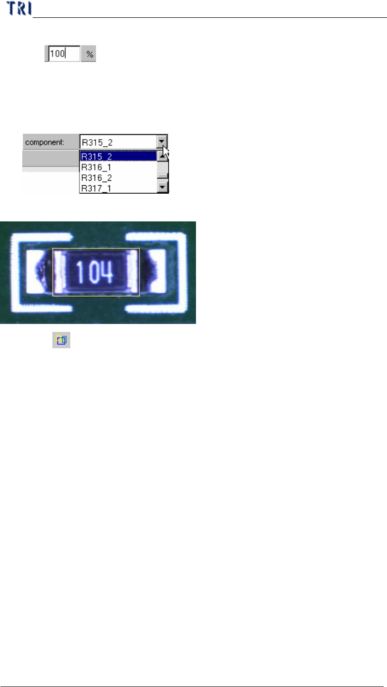
10.8.8. %
l You can change the value to reduce or enlarge the size of all boxes. When
Chapter 3 AOI ATPG Function instruction
TR7500 USER MANUAL
200
you save the library, the current size will be saved.
10.9. Example for editing component library
10.9.1. Example 1 – Chip
(1) Choose a component that is not shifted or skew and have beautiful shape.
(2) Then resize the body window to match the component area.
(3) Press [ Add all] to add missing and void window. The system will create one
missing window on the body window and two void windows at the tow short
sides of missing window separately.
Chapter 3 AOI ATPG Function instruction
TR7500 USER MANUAL
201
(4) Adjust the size of void windows to contain black area.
Void Window
Missing