TR7500E_Manual_en_v28.pdf - 第52页
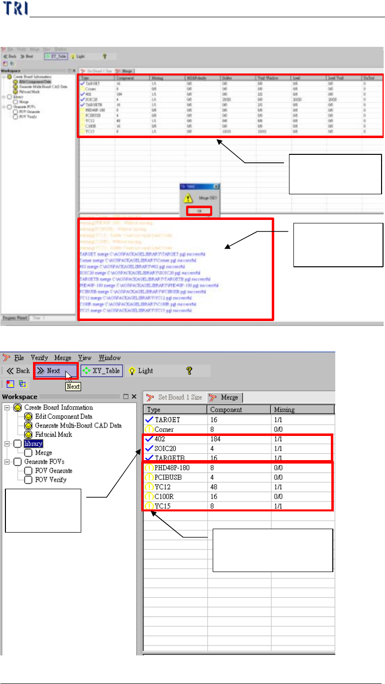
C h a p t e r 1 AO I S t a nd a r d P r o j ec t Cr ea t i on T R 7500 U S E R M A N U AL 45 ( 3) M e r g i ng f i n i s h , C A D d e v i c e l i n k wi t h c o m po n e n t l i b r a r y . ( 4) G o t o n e x t s t e p …
Chapter 1 AOI Standard Project Creation
TR7500 USER MANUAL
44
6. Edit (create or modify a new) for Component Library
l See Chapter 3 10.
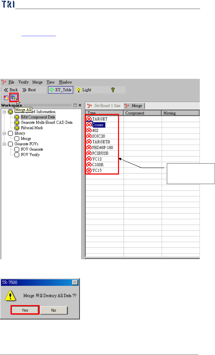
7. Merge with Component Library
l Merge CAD file with component library (component has been editing finish).
(1) Selection merge button.
(2) Warning message before merge component library.
CAD component
name
Chapter 1 AOI Standard Project Creation
TR7500 USER MANUAL
45
(3) Merging finish, CAD device link with component library.
(4) Go to next step.
Component
Merge status list
History list in
merging process
Component
merges OK
Warning component
after merging
Chapter 1 AOI Standard Project Creation
TR7500 USER MANUAL
46
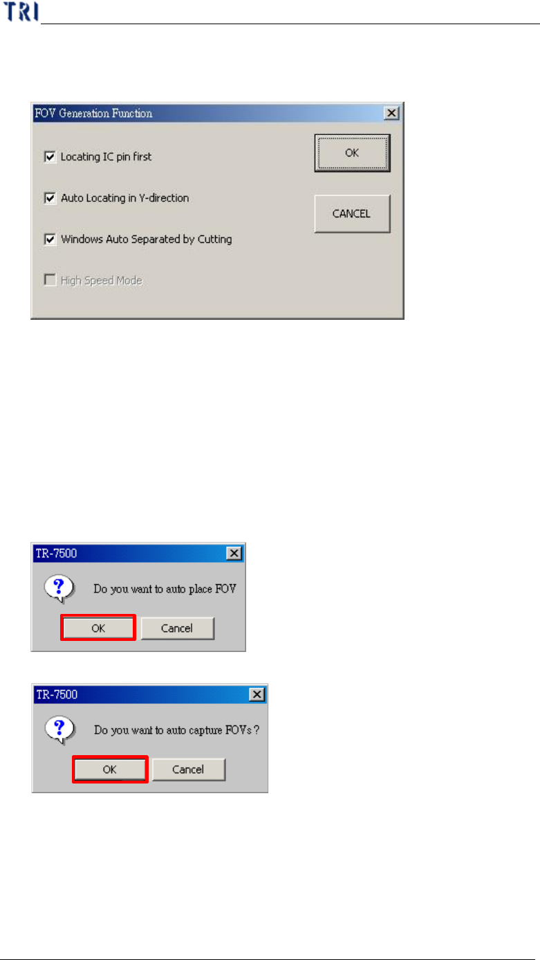
8. FOV Generate
(1) Setting the best FOV distribution rule for AOI inspection.
There are three functions for FOV generation. More check boxes you select,
it will take more time in generation process. The three functions are:
a. Locating IC pin first– It will take fewer FOVs to merge with IC pin
windows, including LEAD and SOLDER.
b. Auto Locating in Y-direction– FOV location will be shifted in Y direction
if it’s necessary.
c. Windows auto separated by cutting– If a inspection window group is cut,
it will separate into two groups.
(2) Warning message for auto place inspection FOV.
(3) Creating the panel FOV image.
(4) If the gap between multi-boards and there are components laid on the edge of the
board, the distance of FOVs will be too closed. The system has to slow down the
speed to keep generating FOVs following multi-board rule and the following
window shows up. You have following three choices to select.