TR7500E_Manual_en_v28.pdf - 第93页
C h a p t e r 2 M a nu a l B a r i n t r o d u ce T R 7500 U S E R M A N U AL 86 S t e p 2. M o v e t h e c r o ss li n e t oo l t o o t h e r c o r n e r s a n d p r e ss [ 2 ] , [ 3 ] a n d [ 4 ] b u t t o n r e s p ec…
Chapter 2 Manual Bar introduce
TR7500 USER MANUAL
85
l
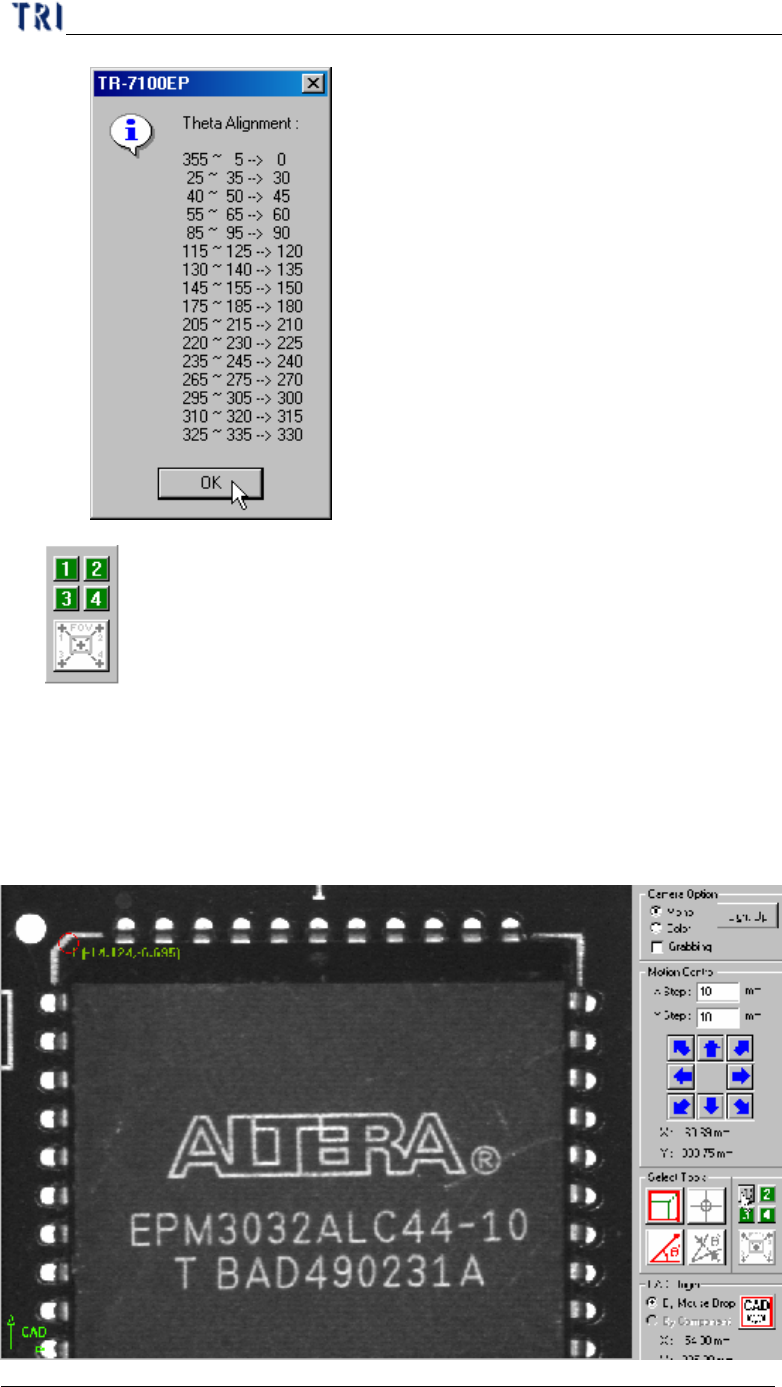
Tool for large component
n It’s a tool to define the coordinates of components. If the component size is
larger than an FOV you can use the tool to get the center of the component.
Step1. Move the cross line tool to the upper-left corner of the component
and press [1] button to get the first corner position.
Chapter 2 Manual Bar introduce
TR7500 USER MANUAL
86
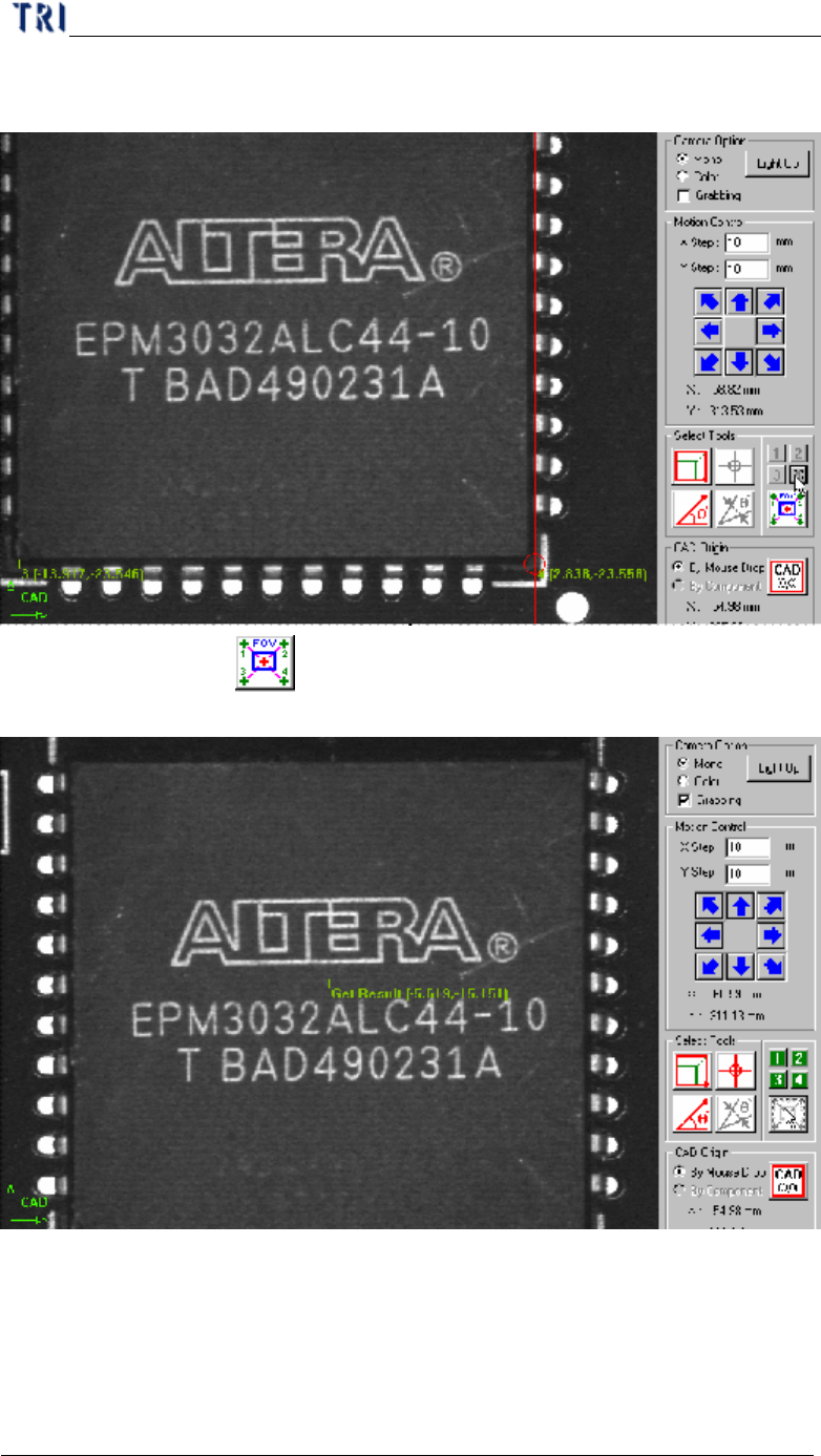
Step2. Move the cross line tool to other corners and press [2], [3] and [4]
button respectively to get the coordinates with the same method.
Step3. Press button and the system will calculate the component
center automatically.
Step4. Press [Add] to add the component after input relative information.
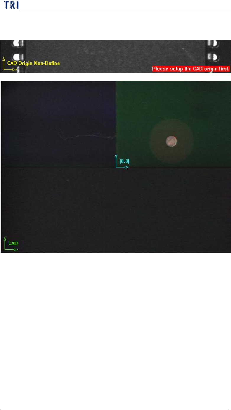
(4) CAD Origin - You should set the origin first for reference before building the
component CAD data. A yellow right angle icon will flash at lower-left corner to
remind you if you don’t set the origin yet. If the origin has already been
Chapter 2 Manual Bar introduce
TR7500 USER MANUAL
87
established the icon is changed to green and the origin is marked as blue icon.
There are two ways to set origin.
l By Mouse Drop - You can use the method when editing a new CAD file.
Move box or cross line tool to the position which you want to set on then press
[CAD(0,0)] and the system will record the coordinates of the origin.
l By Component - You can use the method when loading an existing AOI file
for continuous editing. Select a component at component list field and move a
tool to the component center. Press [CAD(0,0)] button then the system will
record the coordinates of the origin.