TR7500E_Manual_en_v28.pdf - 第16页
C h a p t e r 1 AO I S t a nd a r d P r o j ec t Cr ea t i on T R 7500 U S E R M A N U AL 9 ( 4) G o t o n e x t s t e p . ( 5) S y s t e m c o n f i r m d i a l o g w i n do w . F i n i s h b o a r d v i e w e r a n d t…
Chapter 1 AOI Standard Project Creation
TR7500 USER MANUAL
8
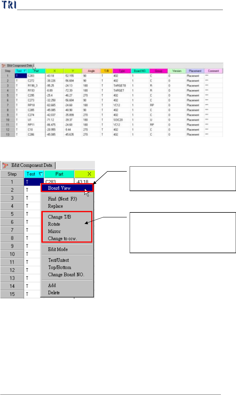
3. Edit Component Data
You should edit the AOI file to meet the position of components in upper left
corner board.
(1) Component Data list.
(2) Board pad Viewer.
(3) Pre-find Component position for board alignment.
Click mouse right side button and
choosing Board View (Top/Bottom)
Board CAD top or bottom side
change, or Board rotation 0~360°
, or
board Mirror, or component rotation
rule
Chapter 1 AOI Standard Project Creation
TR7500 USER MANUAL
9
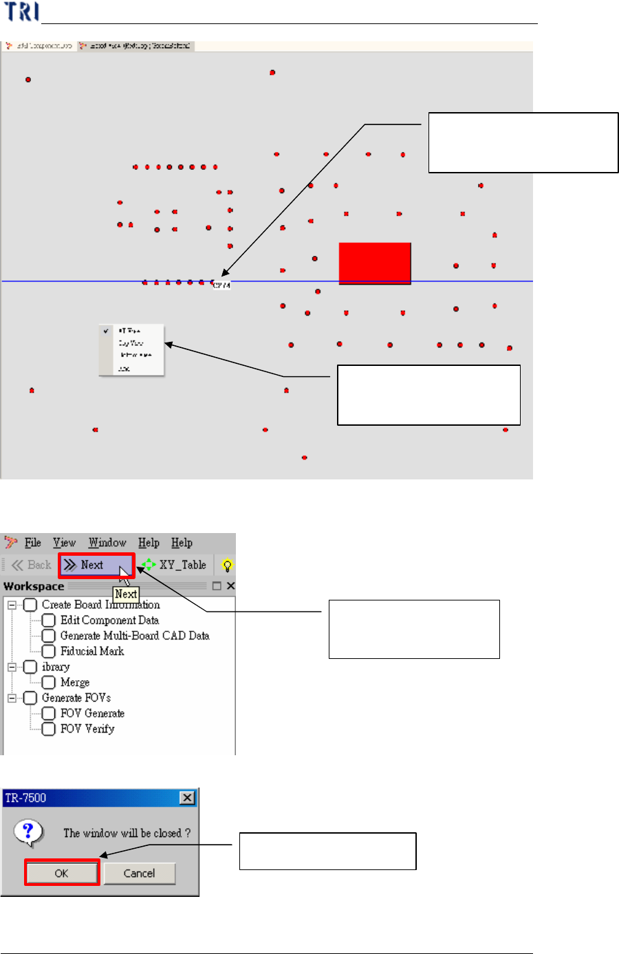
(4) Go to next step.
(5) System confirm dialog window.
Finish board viewer and
then go to next step
Choosing yes to confirm
See if component position
is correct.
Clicking the right button
to get more information
Chapter 1 AOI Standard Project Creation
TR7500 USER MANUAL
10
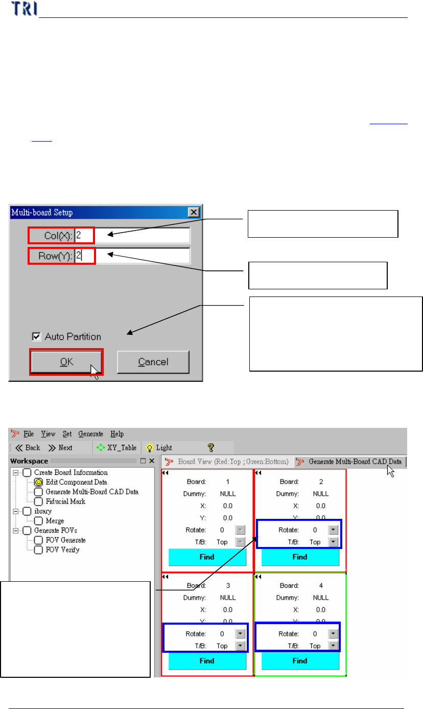
4. Generate Multi-Board CAD Data
l Since the CAD file you collect before is for single board, you have to create
multi-board data.
l If the PCB is a single board you can only input 1 in column and row field
separately and press [Next] to enter the next step, Fiducial Mark Setting (Chapter
1 5. ).
4.1. Setting Multi-board arranged information
(1) Setting Multi-Board matrix (X direction & Y direction board counting).
(2) Setting board rotation first in multi-board.
(3) Setting board 3 rotation.
Multi-board column quantity
Multi-board Row quantity
Setting first board and last board,
the system will be automatic find
the relationship between board
and b
oard
Setting CAD file including
board rotation angle (0
~270) and side (Top/Bottom)
for mapping the multi-board,
if need.