TR7500E_Manual_en_v28.pdf - 第122页
C h a p t e r 2 M a nu a l B a r i n t r o d u ce T R 7500 U S E R M A N U AL 1 15 “ Y e a r - M o n t h - D a t e - T i me ” . 7 . 1 3 . C o m p o n e n t St a t u s l I t c a n b e o n l y s e l e c t e d i n t r a i n…
Chapter 2 Manual Bar introduce
TR7500 USER MANUAL
114
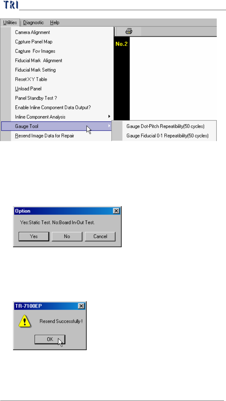
7.10.1. Gauge Fiducial 0-1 Repeatability (50 cycles)
l System measure the distance between two fiducial marks for 50 times and output
the result in [C:\AOI] folder. The first measurement file name is [fireport1.txt]
and the next file will be [fireport2.txt], [fireport3.txt] and so on. You can select
static or board in and out test.
7.11. Resend Image Data for Repair
l It is enabled when you select [Parameter/User Mode/Link to Repair Station].
Press the item and the system will send the data to repair station (Including *dir.1,
*.win, *.img, *.bmp).
7.12. Enable Inspection Data Collection
l You can select the item to save the result for all components as text file. The file
will be saved in the folder that project is saved in and the file name is
Chapter 2 Manual Bar introduce
TR7500 USER MANUAL
115
“Year-Month-Date-Time”.
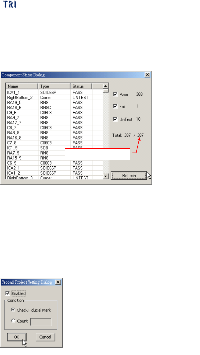
7.13. Component Status
l It can be only selected in train dialog.
l After selecting [Pass], [Fail] and [Untest] you can press [Refresh]. The system
will display the number of components which is passing, fail or untest.
Number of components
7.14. Generate Real Image Data
l Generate the image to ICT or ATE machine.
7.15. Inline Component Data Output to SPC
l Out put the [Cpk Data Collection] to SPC system.
7.16. Second Project Setting
l Select two projects to be open in turn automatically. The function is under
construction.
Chapter 2 Manual Bar introduce
TR7500 USER MANUAL
116
l Enable – Check to start the function. You can load two projects at the same time
and the system will change the project to inspect according to the conditions.
l Check Fiducial Mark – When it can’t find fiducial mark it will change to use
second project.
l Count – Select and input number. When it inspect with first project for specified
times it will change to use second project.
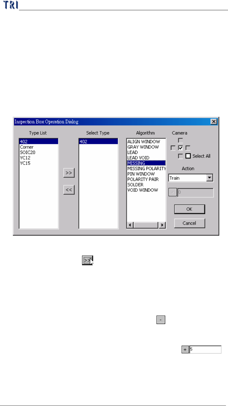
7.17. Inspection Box Operation
l Change the parameters for specific inspection window of specific component
type.
n Type List – System shows all the types in the project.
n Select Type – Select a type you want to change. Select a type in [Type List]
field first then press
to move the type to [Select Type] field.
n Algorithm – Select the inspection window types that you want to modify
here. Camera – Select the camera that you want to modify.
n Camera – Select the camera.
n Action – Select one action.
(1) Change Passlevel – Change pass level. When selecting this item, the
toolbar below will be enabled. Click on the
button to switch plus
or minus sign. Plus sign means to add the number that you input back
and the minus sign means to reduce the number that you input back.
For example, the original score is 60. If the setting is ,
the score will be changed to 65. If the number that you input is 0, the
parameter will be change to the original score. The corresponding
parameter is the followings.
Ø Missing, Missing_Polarity, Lead – Score