FLEXLINE-CAD_INM.pdf - 第100页
A-3 2. St art the "New " scr een of the i nput form at *1 Select the "Format" - "New" command. Figure A - 5 Selecting "New" Fi rst, the following screen is displayed. Click the &…

A-2
Figure A-3 Placement data of Tutorial.txt
Figure A-4 Component data of Tutorial.txt
Component Name and Comment
Q1,"2N2886"
Q2,"BC147"
U1,"74HCT241"
C1,"CAP 22PF, 5%, 50V"
C2,"CAP 0.1MF, 10%, 50V"
C3,"220 MF"
C4,"ECU-V1H103KBW .01 uF"
C5,"CAP 2.2MF, 10%, 50V"
D1,"1N4148 signal diode"
D2,"1N4001X200V "
U2,"LM781CTB TO-220X VAL"
U3,"LTC1421CG"
U4,"MOC3020N"
Q3,"FETP_220 IRF9523"
XTAL1,"XFMR2WCT"
R1,"RES400 1.2K"
R2,"RES 2K 1% 1/10W"
R3,"RES 332 OHM 1% 1/10W"
R4,"RES400 1.2K"
R5,"RES 2K 1% 1/10W"
R6,"RES 332 OHM 1% 1/10W"
R7,"RES400 1.2K"
R8,"RES 2K 1% 1/10W"
R9,"RES 332 OHM 1% 1/10W"
Date 3/8/98
!TAG ID +XXXXXX+YYYYYY+AAA+S CCCCCCCCCCCCCCCC
PLC_0001+005000+000640+000 T Q1
PLC_0002+004350+001230+090 T Q2
PLC_0003+032560+023440+000 T U1
PLC_0004+007670+086540+270 B C1
PLC_0005+003450+075630+090 T C2
PLC_0006+035030+034350+000 T C3
PLC_0007+007600+054750+180 B U2
PLC_0008+023550+034600+090 T C4
PLC_0009+034670+003340+000 T C5
PLC_0010+098970+003450+090 B U3
PLC_0011+066560+045460+270 T U4
PLC_0012+045650+067430+090 B D1
PLC_0013+003660+023450+000 T D2
PLC_0014+004523+046560+090 B Q3
PLC_0015+026640+034660+000 T XTAL1
PLC_0016+012340+032370+090 B R1
PLC_0017+004560+037370+070 T R2
PLC_0018+001230+022440+045 T R3
PLC_0019+012340+059860+090 T R4
PLC_0020+004560+066660+070 B R5
PLC_0021+001230+034550+045 T R6
PLC_0022+012340+023450+090 B R7
PLC_0023+004560+023560+070 T R8
PLC_0024+001230+087450+045 T R9
A-3
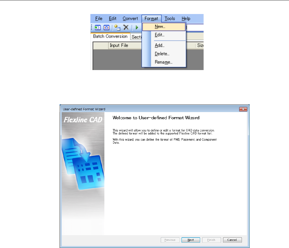
2. Start the "New" screen of the input format *1
Select the "Format" - "New" command.
Figure A-5 Selecting "New"
First, the following screen is displayed. Click the "Next" button.
Figure A-6 Start screen for new format
*1 The screen displayed with the Version 5.10 or earlier is different from that with the Version
6.00 or later.
A-4
3. Global Setup Screen
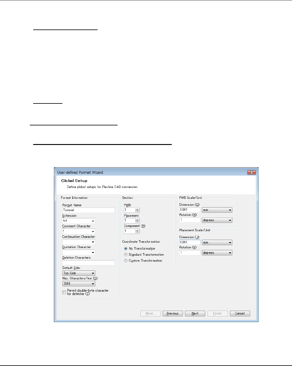
Next, the "Global setup" screen is displayed. Now, set each item as follows:
● "Format Information"
"Format name" → Tutorial
"Extension" → txt
"Comment character" → !
"Default side" → Top side
"Max characters/line" → 2048
Leave the other items blank.
● "Section"
Set each of the "PWB," "Placement," and "Component" to 1.
● "Coordinate Transformation"
Specify the "No Transformation" for the "Coordinate Transformation."
● "PWB Scale/Unit" and "Placement Scale/Unit"
"Dimension" → Set the scale to 0.001 and the unit to mm.
"Rotation" → Set the scale to 1 and the unit to degrees.
Figure A-7 Global Setup screen
When completing the setup, click the "Next" button.
4. Transformation Screen
When the "Standard Transformation" is specified in the "Coordinate Transformation," the
"Standard Transformation setting screen" is displayed. When the "Custom Transformation" is
specified, the "Custom Transformation setting (PWB) screen" is displayed. If the dimension
must be converted, perform a setting for it. (For details, refer to Section 7.3.) Now, no
transformation is required, the transformation screen is not displayed but the "Section definition
screen" is displayed.