FLEXLINE-CAD_INM.pdf - 第102页
A-5 5. P WB Secti on Next, the screen t o define PW B dat a (first, "Section definition screen") is displayed. Click the "Refer" button to display the "Open" dialog box. Select Tutor ial.txt…
A-4
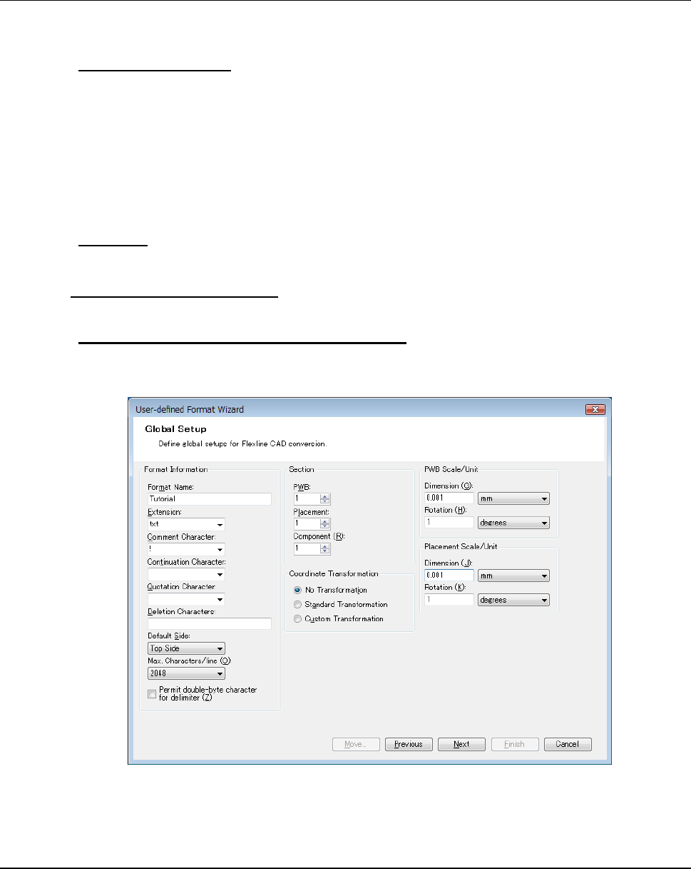
3. Global Setup Screen
Next, the "Global setup" screen is displayed. Now, set each item as follows:
● "Format Information"
"Format name" → Tutorial
"Extension" → txt
"Comment character" → !
"Default side" → Top side
"Max characters/line" → 2048
Leave the other items blank.
● "Section"
Set each of the "PWB," "Placement," and "Component" to 1.
● "Coordinate Transformation"
Specify the "No Transformation" for the "Coordinate Transformation."
● "PWB Scale/Unit" and "Placement Scale/Unit"
"Dimension" → Set the scale to 0.001 and the unit to mm.
"Rotation" → Set the scale to 1 and the unit to degrees.
Figure A-7 Global Setup screen
When completing the setup, click the "Next" button.
4. Transformation Screen
When the "Standard Transformation" is specified in the "Coordinate Transformation," the
"Standard Transformation setting screen" is displayed. When the "Custom Transformation" is
specified, the "Custom Transformation setting (PWB) screen" is displayed. If the dimension
must be converted, perform a setting for it. (For details, refer to Section 7.3.) Now, no
transformation is required, the transformation screen is not displayed but the "Section definition
screen" is displayed.
A-5
5. PWB Section
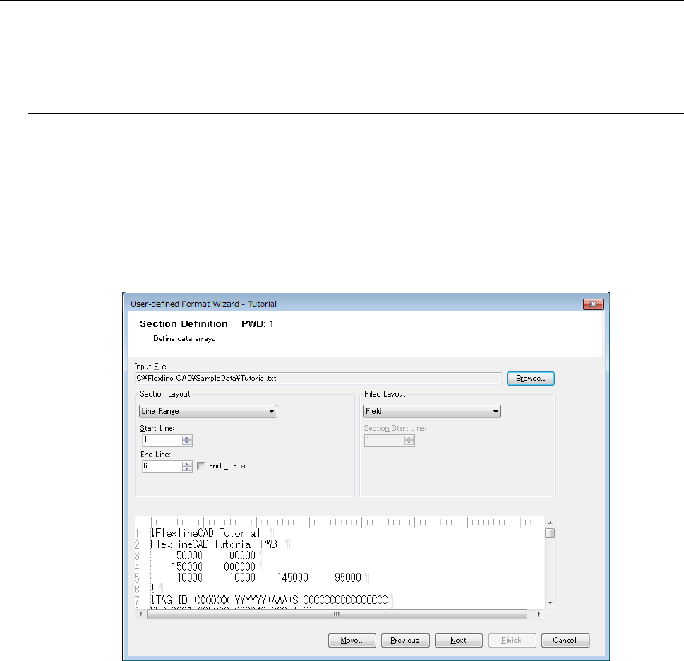
Next, the screen to define PWB data (first, "Section definition screen") is displayed. Click the
"Refer" button to display the "Open" dialog box. Select Tutorial.txt provided in the {Flexline CAD
install folder}\SampleData\" folder.
5.1 PWB Section
● Section layout
In this example, PWB data is provided on line 1 to line 6 (actually line 2 to line 5.
Accordingly, select the "Line range" in the "Section layout" list and enter 1 in the "Start line"
and 6 in the "End line."
● Field layout
From the "Field layout list", select "Field."
Figure A-8 Section definition screen (PWB)
After completing the setting, click the "Next" button.
A-6
5.2 Field definition screen
The PWB data of Tutorial.txt contains "PWB ID", "PWB outer dimensions", "PWB layout offset",
and "BOC mark coordinates." Try to define them in "Field."
5.2.1 Specifying the field position
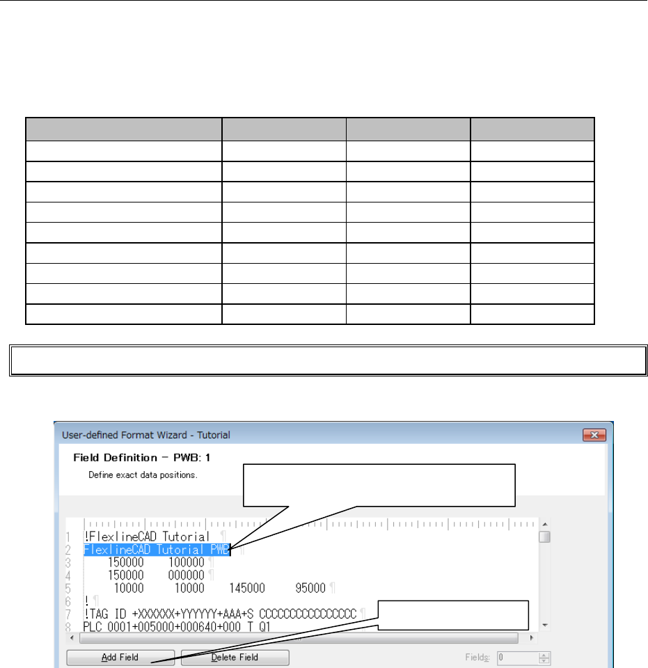
Click and drag the mouse and define the field. In this example, there are nine fields.
Data
Section start line
Start column
End column
Flexline CAD Tutorial PCB
2
1
24
150000
3
5
10
100000
3
15
20
150000
4
5
10
000000
4
15
20
10000
5
6
10
10000
5
16
20
145000
5
25
30
95000
5
36
40
* "Line" and "Column" are data position information and values are entered automatically.
Try to define the first field. (Specify the position and define the contents on the next screen.)
Figure A-9 Field definition screen
Define the above nine fields according to the same procedure.
①
Click on the first character "F."
②
Drag it to "B" by clicking to select this line.
③
Click on "Add field."